EUCHNER MGB-E series, Operating Instructions Manual
The EUCHNER MGB-E series offers reliable safety solutions for machine operation. To ensure its proper usage, browse our user-friendly Operating Instructions Manual and download it for free on our website. Safeguard your workplace with this intuitive manual and enhance your machine's performance. Download from manualshive.com.
Share
Download


Reviews:
No comments
Related manuals for MGB-E series

BLE WM
Brand: Sentrilock Pages: 9

SVPRO3
Brand: AutoLoc Pages: 3

SmartLocker AX SmartIntego
Brand: Simons Voss Technologies Pages: 53

3400 Series
Brand: hager Pages: 2
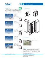
DL-200-1
Brand: Gianni Industries Pages: 2

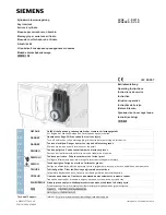
3VT9200-3HC10
Brand: Siemens Pages: 4

3VW9011-0BB10
Brand: Siemens Pages: 7

3VA9088-0LB10
Brand: Siemens Pages: 4

3VA5 125
Brand: Siemens Pages: 5

3VA9980-0LF20
Brand: Siemens Pages: 6
3VA9 7-0LF10 Series
Brand: Siemens Pages: 8

miniPAD BeCode
Brand: beloxx Pages: 5

OU-4200-NA
Brand: COMPX Pages: 1

ES-DLS-02
Brand: eTIGER Pages: 13

Securitron UnLatch
Brand: Assa Abloy Pages: 8

Union CodeGUARD 5
Brand: Assa Abloy Pages: 16

RapidRoll 355
Brand: Albany Pages: 23

IQ lock AUT
Brand: GEZE Pages: 52


