background image

QUICK START GUIDE 

MODEL 195Es


Before You Begin 


The ESTeem Model 195Es wireless Ethernet radio modem is compatible with many different applications.  The most 
common application is to bridge two or more Ethernet devices.  This guide will demonstrate the basic configuration and 
testing of a pair of 195Es’s.  For more detailed information, please see the ESTeem Model 195Es User’s Manual. 


This guide assumes you have a working knowledge of Ethernet networking, TCP/IP protocol and how to identify and set the 
TCP/IP address on your computer. 


The 195Es can be configured using any current web browser software such as Internet Explorer, Netscape or Mozilla. 


The following procedure will provide an initial communication link between two or more Model 195’s for testing purposes.  
All the example commands listed in this guide can be adjusted to fit your communication network.  Please consult the 
ESTeem Model 195Es User’s Manual for more details. 
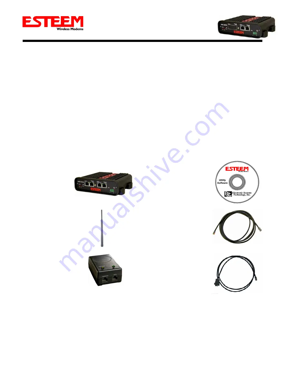
 
Unpack Contents 
 
Each node in your ESTeem Model 195Es’s network may have different hardware components based upon the final installation 
location (i.e Outdoor, Indoor, Point-to-point or Muti-Point).  Antenna types, cable lengths, power supplies may be different, but 
the following items will be required for basic setup: 


Model 195Es 


AA109 Resource Disk 


Antenna  

(AA20DMEs 

Displayed) 


(2) Ethernet Cables 


Power Supply 

(AA175 Displayed) 


Serial Interface Cable 

(AA6021.1) 


Note:  Your accessory model numbers may vary from the above, but you will need to locate each of above items to continue 
configuration.
  

Summary of Contents for 195Es

Page 1: ...wing procedure will provide an initial communication link between two or more Model 195 s for testing purposes All the example commands listed in this guide can be adjusted to fit your communication network Please consult the ESTeem Model 195Es User s Manual for more details Unpack Contents Each node in your ESTeem Model 195Es s network may have different hardware components based upon the final i...

Page 2: ... VDC Input Auxiliary Connector Reset Switch RS 232 Configuration RJ 45 10 100BaseT Ethernet Port Transmit LED Receive LED Status LED Power over Ethernet LED Aux Power LED RS 232 Data Port Second Ethernet Port Antenna Overview ...

Page 3: ...Begin Programming 1 Assemble the ESTeem Model 195Es using the following Power and Data Connection Antenna Connections ...

Page 4: ...ach 195Es If the factory default address matches your network configuration please proceed to Using Setup otherwise continue to step 4 4 Install the ESTeem Discovery Utility The ESTeem Discovery Utility will allow you to configure the IP address on the Model 195Es to match your network Install the Discovery Utility on your computer by inserting the Resource Disk in your CD drive Note The ESTeem Re...

Page 5: ...odel 195Es will be displayed in the program by the Ethernet MAC address and Current IP Address Figure 3 Note The SSID and Mode of Operation will be adjusted later in the configuration Double click on the 195Es you wish to program and the Configure IP Address window will be displayed Figure 4 Enter an IP address and Subnet Mask for the 195Es that matches your network subnet and press the OK button ...

Page 6: ...ter admin for both the username and password and press the OK button 2 Select Setup on the top menu 3 Press the drop down menu and select AP Bridge and press the Next button Step 1 Sign In Screen Step 3 Select AP Bridge ...

Page 7: ...t the DHCP services to OFF and press the Next button 5 Verify the IP address and netmask for the 195Es listed as bridge device are correct press the Next button Step 4 Turn DHCP Off Step 5 Verify IP Address ...

Page 8: ...ation SSID The default SSID is ESTeem and we will use this for demonstration Enter the SSID as listed above and turn off the wireless security features by selecting the NO radial Press the Next button to continue Note It is recommended that security be used in all wireless applications This procedure will forgo the security configuration for brevity Please see the example applications and the secu...

Page 9: ...t the Upstream Timing Master to the WLANC MAC address of the Timing Master 00 04 3f 00 01 02 in the following example Example Addresses Name Serial Number IP Address Ethernet MAC WLAN MAC Timing Master E 14096 172 16 48 189 00 04 3f 00 01 01 00 04 3f 00 01 02 Opposite 195Es We Will Create Wireless Link E 14034 172 16 38 114 00 04 3F 00 0B 00 00 04 3F 00 11 02 Example E 14096 Configuration Example ...

Page 10: ...le Link radial to Enable and press the Create Repeater Peer button Press the Next button 10 Press the Commit Changes button and the modem will save all the changes made and reboot The reboot time is approximately 1 minute to be ready for operation 11 Complete all steps in this Setup Programming section for the other Model 195Es s you will be testing before moving on the Testing Communication secti...

Page 11: ...tus of the communication link signal strength and last update time you can open the Status Screen from the Web Interface After press the Status tab at the top of the screen the Status Summary will be displayed showing the status of all ports and memory in the 195Es Under the Wireless Status heading click on the View Peer Table Figure 5 The Peer Table will list all 195Es in client mode connected to...

Page 12: ...ESTeems is to conduct a Ping test to the opposite modem s IP address This will test all links in the Ethernet bridge Technical Support User s Manual and Technical Documentation http www esteem com E Mail Support Support esteem com Phone Support 8AM to 5PM PST Monday Friday 509 735 9092 ...

Reviews: