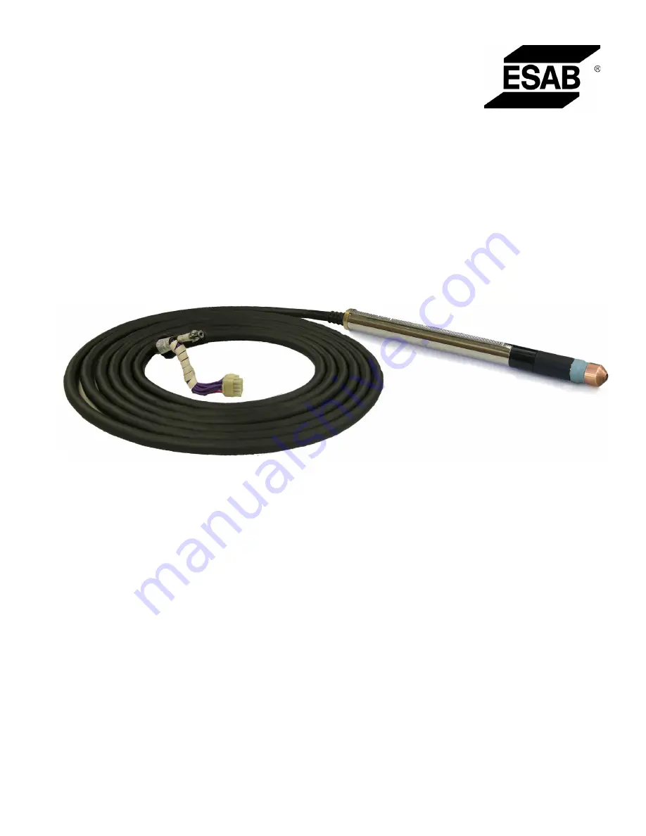
background image

PT-37

Plasmarc Cutting Torches

0558005966   


05/2011

Instruction Manual

P/N 0558004860 - PT-37 Torch with rack 4.5' (1.4 m)

P/N 0558004861 - PT-37 Torch with rack 17' (5.2 m)

P/N 0558004862 - PT-37 Torch with rack 25' (7.6 m)

P/N 0558004863 - PT-37 Torch with rack 50' (15.2 m)

P/N 0558004894 - PT-37 Torch w/o rack 4.5' (1.4 m)

P/N 0558004895 - PT-37 Torch  w/o rack 17' (5.2 m) 

P/N 0558004896 - PT-37 Torch  w/o rack 25' (7.6 m)

P/N 0558004897 - PT-37 Torch  w/o rack 50' (15.2 m)

Summary of Contents for PT-37

Page 1: ... N 0558004861 PT 37 Torch with rack 17 5 2 m P N 0558004862 PT 37 Torch with rack 25 7 6 m P N 0558004863 PT 37 Torch with rack 50 15 2 m P N 0558004894 PT 37 Torch w o rack 4 5 1 4 m P N 0558004895 PT 37 Torch w o rack 17 5 2 m P N 0558004896 PT 37 Torch w o rack 25 7 6 m P N 0558004897 PT 37 Torch w o rack 50 15 2 m ...

Page 2: ... from improper use faulty maintenance damage improper repair or alteration by anyone other than the manufacturer or a ser vice facility designated by the manufacturer Be sure this information reaches the operator You can get extra copies through your supplier These INSTRUCTIONS are for experienced operators If you are not fully familiar with the principles of operation and safe practices for arc w...

Page 3: ...3 Torch Installation Powercut 900 1300 1600 26 3 4 Torch Installation Remote Junction Box 28 SECTION 4 OPERATION 29 4 0 Cutting with the PT 37 29 4 1 Installing Consumables 29 4 2 Cut Data 31 4 2 1 Pressure Reduction for 4 5 and 17 Torch Lengths 31 4 3 Operation of Power Source 31 SECTION 5 MAINTENANCE 65 5 0 General 65 5 1 Dirt or Contamination 65 5 2 Inspection Cleaning and Replacement of Consum...

Page 4: ...4 TABLE OF CONTENTS ...

Page 5: ...g 5 Protect other personnel from arc rays and hot sparks with a suitable non flammable partition or curtains 6 Usegogglesoversafetyglasseswhenchippingslag orgrinding Chippedslagmaybehotandcanflyfar Bystanders should also wear goggles over safety glasses FIRES AND EXPLOSIONS Heat from flames and arcs can start fires Hot slag or sparks canalso causefires and explosions Therefore 1 Remove all combust...

Page 6: ...retoEMFmayhaveotherhealtheffectswhich are unknown 3 Welders should use the following procedures to minimize exposure to EMF A Route the electrode and work cables together Secure them with tape when possible B Never coil the torch or work cable around your body C Do not place your body between the torch and work cables Route cables on the same side of your body D Connecttheworkcabletotheworkpieceas...

Page 7: ... available from Compressed Gas Association 1235 Jefferson Davis Highway Arlington VA 22202 EQUIPMENT MAINTENANCE Faulty or improperly maintained equipment can cause injury or death Therefore 1 Alwayshavequalifiedpersonnelperformtheinstal lation troubleshooting and maintenance work Do not perform any electrical work unless you are qualified to perform such work 2 Before performing any maintenance w...

Page 8: ...d Safe Practices for Welding and Cutting of Containers That Have Held Hazardous Substances Meaning of symbols As used throughout this manual Means Atten tion Be Alert Your safety is involved Meansimmediatehazardswhich if not avoided will result in im mediate serious personal injury or loss of life Means potential hazards which could result in personal injury or loss of life Meanshazardswhichcouldr...

Page 9: ...na adecuadano flamable como división 6 Usecaretaprotectoraademásdesusgafasdesegu ridad cuando esté removiendo escoria o puliendo La escoria puede estar caliente y desprenderse con velocidad Personas cercanas deberán usar gafas de seguridad y careta protectora FUEGO Y EXPLOSIONES El calor de lasflamasyelarco puedenocacionar fuegos Escoria caliente y las chispas pueden causar fuegos y explosiones Po...

Page 10: ...lectromagnéticos EMF puede causar otros efectos de salud aún desconocidos 3 Los soldadores deberán usar los siguientes proced imientos para minimizar exponerse al EMF A Mantenga el electrodo y el cable a la pieza de trabajo juntos hasta llegar a la pieza que usted quiere soldar Asegúrelos uno junto al otro con cinta adhesiva cuando sea posible B Nunca envuelva los cables de soldar alrededor de su ...

Page 11: ...quipo defectuoso o mal mantenido puede causar daño o muerte Por lo tanto 1 Siempre tenga personal cualificado para efec tuar l a instalación diagnóstico y mantenimiento del equipo No ejecute ningún trabajo eléctrico a menos que usted esté cualificado para hacer el trabajo 2 Antes de dar mantenimiento en el interior de la fuente de poder desconecte la fuente de poder del suministro de electricidad ...

Page 12: ...ata de su seguridad Significa riesgo inmediato que de no ser evadido puede resultar inmediatamente en serio daño personal o la muerte Significa el riesgo de un peligro potencial que puede resultar en serio daño personal o la muerte Significa el posible riesgo que puede resultar en menores daños a la persona Sección 1 sEGURIDAD ...

Page 13: ...rmations de précaution provenant desréférencesdanslasectiondesInformationsdesécu rité supplémentaires Avant de procéder à l installation ou d utiliser l unité assurez vous de lire et de suivre les précautionsdesécuritéci dessous danslesmanuels les fichesd informationsurlasécuritédumatérieletsurles étiquettes etc Tout défaut d observer ces précautions de sécurité peut entraîner des blessures graves...

Page 14: ...e 4 Consultez ANSI ASC Standard Z49 1 à la page suivante pour des recommandations spécifiques concernant la ventilation 1 Assurez vous que le châssis de la source d alimentation est branché au système de mise à la terre de l alimentation d entrée 2 Branchez la pièce à traiter à une bonne mise de terre électrique 3 Branchez le câble de masse à la pièce à traiter et assurezunebonneconnexionafind évi...

Page 15: ...s ou des gaz contenant des chimiques consid éres par l état de la Californie comme étant une cause des malformations congénitales et dans certains cas du cancer California Health Safety Code 25249 5 et seq MANIPULATION DES CYLINDRES La manipulation d un cylindre sans observerlesprécautionsnécessaires peut produire des fissures et un échappement dangereux des gaz Unebrisuresoudaineducylindre delaso...

Page 16: ...n Soyez vigilant Votre sécurité est en jeu Signifie un danger immédiat La situation peut entraîner des blessures graves ou mortelles Signifieundangerpotentielquipeutentraînerdes blessures graves ou mortelles Signifieundangerquipeutentraînerdesblessures corporelles mineures DANGER AVERTISSEMENT ATTENTION ...

Page 17: ...te starting system allows the torch to be located up to 150 45m away from the power sup ply Machined torch body with 1 3 8 35mm metal handle available with and without 32 pitch rack to fit industry standard torch holders Robust machined torch components provide for reliability durability and ease of maintenance Metal nozzle and shield stand up to the toughest cutting conditions Wear parts are avai...

Page 18: ...4895 PT 37 Torch w o rack 25 7 6 m 0558004896 PT 37 Torch w o rack 50 15 2 m 0558004897 SECTION 2 DESCRIPTION Pierces and Cuts 3 4 in 19 mm severs 1 1 4 in 32 mm Current Capacity 100 amps 100 duty cycle Nominal Flow Rate with 100 amp consumables 490 cfh 80 psig 231 l min 5 5 bar Length of Service Lines 4 5 ft 1 4 m 17 ft 5 2 m 25 ft 7 6 m or 50 ft 15 2 m Optional Service Line Extensions 50 ft 15 m...

Page 19: ...58008141 Powercut 1600 208 230 460 V Mechanized Console 0558007883 208 230 460V Mechanized Console Bilingual 0558007883F 400 V Mechanized Console 0558008933 400 V CE Mechanized Console 0558007884 575 V Mechanized Console Bilingual 0558008142 Powercut 900 208 230 V Mechanized Console 0558008126 208 230 V Mechanized Console Bilingual 0558008126F 230 V CE Mechanized Console 0558008139 460 V Mechanize...

Page 20: ...supplies Extension Cable 50 ft 15m for Remote Junction Box p n 0558004888 75 ft 23m for Remote Junction Box p n 0558009266 100 ft 30m for Remote Junction Box p n 0558004889 Torch Holder Assembly p n 0558005926 Plate Rider p n 0560936972 Used to maintain a constant standoff while cutting thin materials or using machines without automatic height control Gas Flow Measuring Kit p n 0558000739 Valuable...

Page 21: ...0 Amp 1 1 1 1 0558006600 Retaining Cup with Threads 5 5 5 5 0558006603 Shield 30 40 Amp 5 5 5 5 0558006602 Shield 50 90 Amp 5 0558006601 Shield 100 Amp 5 5 5 5 0558003694 O ring 674 ID x 103 W Neoprene 1 1 1 1 0558000443 Grease Silicon Dow DC 111 0 25 oz PT 37 Consumable Sets 0558004886 100 Amp Value Pack 0558004885 100 Amp 0558008830 90 Amp 0558008369 70 Amp 0558008831 60 Amp 0558004884 50 Amp 05...

Page 22: ... 5 NOZZLES 50A Ÿ 5 NOZZLES 30 40A Ÿ 1 RETAINING CUP Ÿ 5 SHIELDS 100A Ÿ 5 SHIELDS 50 90A Ÿ 5 SHIELDS 30 40A Ÿ 10 ELECTRODES Ÿ 1 GAS BAFFLE 30 70A Ÿ 5 O RINGS Ÿ 5 NOZZLES 70A Ÿ 5 NOZZLES 50A Ÿ 5 NOZZLES 30 40A Ÿ 1 RETAINING CUP Ÿ 5 SHIELDS 50 90A Ÿ 5 SHIELDS 30 40A Ÿ 10 ELECTRODES Ÿ 1 GAS BAFFLE 30 70A Ÿ 5 O RINGS Ÿ 5 NOZZLES 60A Ÿ 5 NOZZLES 50A Ÿ 5 NOZZLES 30 40A Ÿ 1 RETAINING CUP Ÿ 5 SHIELDS 50 90...

Page 23: ...0 Installation 3 1 Torch Mounting 7 2 183 mm 13 2 335 mm Recommended Minimum Recommended Maximum With Torch Holder Assembly P N 0558005926 With Customer Supplied Holder 7 2 183 mm 13 2 335 mm Recommended Minimum Recommended Maximum 18 1 460 mm 1 38 35 mm 12 0 305 mm 13 7 348 mm 4 4 112 mm Torch Dimensions Mounting Area 6 0 152 mm ...

Page 24: ... on the left side of the ESP 101 2 Insert the torch cable through the torch access opening on the front of the console 3 Connect the air hose to the quick connect fitting 4 Connect the torch cable male receptacle to the panel recep tacle Check orientation of the sockets to ensure a correct fit Power Cable Male Receptacle 3 2 Torch Installation ESP 101 ...

Page 25: ...25 5 Replace the torch lead access door Torch Lead Access Door 6 Insert the work cable into receptacle on the front of the con sole and turn clockwise until secure Work Cable SECTION 3 INSTALLATION ...

Page 26: ... 3 Connect the air hose to the quick connect fitting Place the strain relief in the square cutout in the front of the console Line up the groove of the strain relief with the half square cutout area Torch Cable Male Receptacle strain relief square cutout 3 3 Torch Installation Powercut 900 1300 1600 1 Open torch lead access door on the front panel of the Powercut 1300 1600 Torch Lead Access Door ...

Page 27: ...27 Torch Lead Access Door Work Cable SECTION 3 INSTALLATION 4 Insert work cable into receptacle on the front of the console and turn clockwise until secure 5 Replace torch lead access door ...

Page 28: ...ote junction box Refer to remote junction box instruction manual Note that the solenoid is wired to the power supply extension cable receptacle side of the box 2 Connect the air hose to the quick connect fitting 3 Connect the torch cable male receptacle to the panel receptacle Check orientation of the sockets to en sure a correct fit 4 Replace cover ...

Page 29: ...d Note Ensure that the electrode torch body seat and piston are clean and free of dust or dirt Debris may prevent mating surfaces from having solid contact 4 1 Installing Consumables Tests have shown that with proper use of the torch within rated operating conditions especially arc current and gas flow rate the torch consumable parts do not become loose if they are firmly installed Torch damage an...

Page 30: ...30 section 4 operation ...

Page 31: ...ut Data Use the following pages for initial cutting parameters Variations in material and conditions may require adjust ments to be made to obtain desired results 4 2 1 Pressure Reduction for 4 5 1 4 m and 17 5 2 m Torch Lengths With or without Junction Box installed When using 4 5 1 4 m or 17 5 2 m torch assemblies plasma gas set tings should be reduced 5 10 psi 35 69 bar for optimum performance ...

Page 32: ...a Gas PLASMARC Cutting Torch PT 37 5 Galvanized Steel 30 and 40 Air 80 psi 5 5 bar 1 gas Baffle p n 0558005217 2 Electrode p n 0558005220 3 Nozzle 30 40 AMP p n 0558005218 4 Retaining Cup w threads p n 0558006600 5 SHIELD 30 40 AMP P N 0558006603 ...

Page 33: ...8 0 188 0 090 123 100 0 050 110 140 Metric Cutting Data Material Thickness Cutting Current Initial Height Pierce Height Cutting Height Arc Voltage Pierce Delay Kerf Width Optimum Speed Maximum Speed mm Amps mm mm mm Volts msec mm mm min mm min 0 7 30 4 0 4 0 1 6 117 0 0 8 7600 10300 0 8 30 4 0 4 0 1 6 118 0 0 8 7200 9700 0 9 30 4 0 4 0 1 6 118 0 0 8 6800 8900 1 30 4 0 4 0 1 6 119 0 0 8 6600 8400 1...

Page 34: ...sma Gas PLASMARC Cutting Torch PT 37 5 Carbon Steel 30 and 40 Air 80 psi 5 5 bar 1 gas Baffle p n 0558005217 2 Electrode p n 0558005220 3 Nozzle 30 40 Amp p n 0558005218 4 Retaining Cup w threads p n 0558006600 5 SHIELD 30 40 Amp P N 0558006603 ...

Page 35: ...00 0 057 62 83 4ga 0 224 40 0 195 0 195 0 090 126 125 0 059 55 71 1 4 0 250 40 0 200 0 200 0 090 127 150 0 062 48 60 Metric Cutting Data Material Thickness Cutting Current Initial Height Pierce Height Cutting Height Arc Voltage Pierce Delay Kerf Width Optimum Speed Maximum Speed mm Amps mm mm mm Volts msec mm mm min mm min 0 5 30 4 8 4 8 1 6 118 0 0 8 12300 17000 0 6 30 4 8 4 8 1 6 119 0 0 9 11400...

Page 36: ...ting Torch ESP 101 Plasma System PT 37 Carbon Steel 50 Air 70 psi 4 8 bar 1 gas Baffle 30 70 Amp p n 0558005217 2 Electrode p n 0558005220 3 Nozzle 50 amp p n 0558004878 4 Retaining Cup w threads p n 0558006600 5 SHIELD 50 90 amp P N 0558006602 5 See section 4 2 1 ...

Page 37: ...0 0 072 20 27 5 8 0 625 0 200 0 275 0 075 151 950 0 075 10 12 Metric Cutting Data Material Thickness Initial Height Pierce Height Cutting Height Arc Voltage Pierce Delay Kerf Width Optimum Speed Maximum Speed mm mm mm mm Volts msec mm mm min mm min 1 5 5 1 5 1 1 5 118 0 1 0 9800 11200 2 5 1 5 1 1 8 120 0 1 1 8000 9300 3 5 1 5 1 2 2 126 100 1 4 4400 5600 4 5 1 5 1 2 3 128 100 1 5 3000 4100 5 5 1 5 ...

Page 38: ...04875 3 Nozzle 60 amp p n 0558008417 4 Retaining Cup w threads p n 0558006600 5 SHIELD 50 90 amp P N 0558006602 5 See section 4 2 1 IMPORTANT Reminder for PowerCut 900 users Power Source Ratings 60 Amps 60 duty cycle 50 Amps 100 duty cycle The maximum output of the PowerCut 900 is 60 amps However if your application calls for a duty cycle greater than 60 the output should be reduced to 50 amps or ...

Page 39: ... 156 925 0 084 16 20 Metric Cutting Data Material Thickness Initial Height Pierce Height Cutting Height Arc Voltage Pierce Delay Kerf Width Optimum Speed Maximum Speed mm mm mm mm Volts msec mm mm min mm min 3 5 1 5 1 2 2 125 50 1 3 5200 6400 4 5 1 5 2 2 6 128 75 1 5 3900 5100 5 5 1 5 4 2 9 131 125 1 6 3000 4000 6 5 1 5 5 3 4 135 200 1 7 2300 3000 8 5 1 5 9 3 9 139 250 1 8 1525 2000 10 5 1 6 3 4 1...

Page 40: ...g Torch ESP 101 Plasma System PT 37 Carbon Steel 70 Air 80 psi 5 5 bar 1 gas Baffle 30 70 Amp p n 0558005217 2 Electrode silver p n 0558004875 3 Nozzle 70 amp p n 0558005219 4 Retaining Cup w threads p n 0558006600 5 SHIELD 50 90 amp P N 0558006602 5 See section 4 2 1 ...

Page 41: ...ric Cutting Data Material Thickness Initial Height Pierce Height Cutting Height Arc Voltage Pierce Delay Kerf Width Optimum Speed Maximum Speed mm mm mm mm Volts msec mm mm min mm min 3 5 1 5 0 2 3 124 0 1 3 5900 7200 4 5 1 5 3 2 8 129 50 1 4 4800 6000 5 5 1 5 7 3 3 133 150 1 5 3800 4800 6 5 1 6 0 3 8 137 225 1 6 2700 3700 8 5 1 6 1 4 7 143 300 1 8 1800 2400 10 5 1 6 2 5 4 147 350 2 0 1200 1575 12...

Page 42: ... Torch ESP 101 Plasma System PT 37 Carbon Steel 100 Air 80 psi 5 5 bar 1 gas Baffle 90 100 Amp p n 0558004870 2 Electrode silver p n 0558004875 3 Nozzle 100 amp p n 0558004879 4 Retaining Cup w threads p n 0558006600 5 SHIELD 100 amp P N 0558006601 5 See section 4 2 1 ...

Page 43: ...kness Initial Height Pierce Height Cutting Height Arc Voltage Pierce Delay Kerf Width Optimum Speed Maximum Speed mm mm mm mm Volts msec mm mm min mm min 6 4 8 4 8 2 2 137 75 1 9 3600 4400 8 4 8 4 8 3 2 144 200 2 1 2700 3300 10 4 8 5 0 4 0 150 300 2 3 1900 2425 12 4 8 5 8 4 0 152 300 2 5 1550 1950 14 4 8 6 1 4 0 154 350 2 6 1275 1500 15 4 8 6 1 4 0 155 375 2 7 1125 1300 16 4 8 6 2 3 9 156 425 2 8 ...

Page 44: ...lasma Gas PLASMARC Cutting Torch PT 37 5 Aluminum 30 and 40 Air 80 psi 5 5 bar 1 gas Baffle p n 0558005217 2 Electrode p n 0558005220 3 Nozzle 30 40 AMP p n 0558005218 4 Retaining Cup w threads p n 0558006600 5 SHIELD 30 40 AMP P N 0558006603 ...

Page 45: ...0 128 100 0 054 80 100 1 4 0 250 40 0 200 0 200 0 125 136 150 0 059 50 66 Metric Cutting Data Material Thickness Cutting Current Initial Height Pierce Height Cutting Height Arc Voltage Pierce Delay Kerf Width Optimum Speed Maximum Speed mm Amps mm mm mm Volts msec mm mm min mm min 0 8 30 4 0 4 0 1 6 121 0 0 9 10500 16400 0 9 30 4 0 4 0 1 6 122 0 0 9 9700 14900 1 30 4 0 4 0 1 6 123 0 1 0 8900 13300...

Page 46: ...utting Torch ESP 101 Plasma System PT 37 Aluminum 50 Air 80 psi 5 5 bar 1 gas Baffle 30 70 Amp p n 0558005217 2 Electrode p n 0558005220 3 Nozzle 50 amp p n 0558004878 4 Retaining Cup w threads p n 0558006600 5 SHIELD 50 90 amp P N 0558006602 5 See section 4 2 1 ...

Page 47: ...5 0 200 0 250 0 062 156 350 0 074 36 50 1 2 0 500 0 200 0 280 0 120 160 500 0 084 20 30 Metric Cutting Data Material Thickness Initial Height Pierce Height Cutting Height Arc Voltage Pierce Delay Kerf Width Optimum Speed Maximum Speed mm mm mm mm Volts msec mm mm min mm min 1 5 5 1 5 1 1 3 138 50 1 6 8300 11700 2 5 1 5 1 1 3 138 75 1 6 7200 10000 3 5 1 5 1 1 5 138 150 1 6 5000 6600 4 5 1 5 1 1 7 1...

Page 48: ...875 3 Nozzle 60 amp p n 0558008417 4 Retaining Cup w threads p n 0558006600 5 SHIELD 50 90 amp P N 0558006602 5 See section 4 2 1 IMPORTANT Reminder for PowerCut 900 users Power Source Ratings 60 Amps 60 duty cycle 50 Amps 100 duty cycle The maximum output of the PowerCut 900 is 60 amps However if your application calls for a duty cycle greater than 60 the output should be reduced to 50 amps or le...

Page 49: ... 2 0 500 0 200 0 280 0 138 159 500 0 085 27 46 Metric Cutting Data Material Thickness Initial Height Pierce Height Cutting Height Arc Voltage Pierce Delay Kerf Width Optimum Speed Maximum Speed mm mm mm mm Volts msec mm mm min mm min 3 5 1 5 1 3 5 141 125 1 6 6100 8800 4 5 1 5 1 3 6 145 150 1 7 4600 6300 5 5 1 5 1 3 5 147 150 1 8 3400 4400 6 5 1 5 1 2 5 147 225 1 9 2500 3500 8 5 1 5 7 2 7 151 300 ...

Page 50: ...ing Torch ESP 101 Plasma System PT 37 Aluminum 70 Air 80 psi 5 5 bar 1 gas Baffle 30 70 Amp p n 0558005217 2 Electrode silver p n 0558004875 3 Nozzle 70 amp p n 0558005219 4 Retaining Cup w threads p n 0558006600 5 SHIELD 50 90 amp P N 0558006602 5 See section 4 2 1 ...

Page 51: ... 650 0 098 20 34 Metric Cutting Data Material Thickness Initial Height Pierce Height Cutting Height Arc Voltage Pierce Delay Kerf Width Optimum Speed Maximum Speed mm mm mm mm Volts msec mm mm min mm min 3 5 1 5 1 5 5 144 100 1 6 7300 10900 4 5 1 5 1 5 5 150 100 1 8 5700 7900 5 5 1 5 1 5 1 153 125 2 0 4300 5400 6 5 1 5 1 3 4 148 200 2 0 3000 4400 8 5 1 5 6 3 8 150 275 2 0 1900 3100 10 5 1 6 2 4 7 ...

Page 52: ...sma System PT 37 Aluminum 100 Air 80 psi 5 5 bar section 4 operation 1 gas Baffle 90 100 Amp p n 0558004870 2 Electrode silver p n 0558004875 3 Nozzle 100 amp p n 0558004879 4 Retaining Cup w threads p n 0558006600 5 SHIELD 100 amp P N 0558006601 5 See section 4 2 1 ...

Page 53: ...Pierce Height Cutting Height Arc Voltage Pierce Delay Kerf Width Optimum Speed Maximum Speed mm mm mm mm Volts msec mm mm min mm min 6 5 1 6 4 4 0 143 250 2 3 4500 5700 8 5 1 6 4 4 0 149 300 2 4 3300 4300 10 5 1 6 4 4 0 155 375 2 5 2200 3000 12 5 1 6 4 4 0 157 475 2 6 1525 2375 14 5 1 6 4 4 0 159 550 2 7 1225 1950 15 5 1 6 4 4 0 160 575 2 8 1275 1800 16 5 1 6 4 4 0 161 625 2 8 1250 1625 18 5 1 7 2...

Page 54: ...a Gas PLASMARC Cutting Torch PT 37 5 Stainless Steel 30 and 40 Air 85 psi 5 85 bar 1 gas Baffle p n 0558005217 2 Electrode p n 0558005220 3 Nozzle 30 40 AMP p n 0558005218 4 Retaining Cup w threads p n 0558006600 5 SHIELD 30 40 AMP P N 0558006603 ...

Page 55: ...129 100 0 060 41 62 4ga 0 234 40 0 197 0 197 0 093 133 100 0 063 33 51 3ga 1 4 0 250 40 0 200 0 200 0 094 134 100 0 065 30 46 Metric Cutting Data Material Thickness Cutting Current Initial Height Pierce Height Cutting Height Arc Voltage Pierce Delay Kerf Width Optimum Speed Maximum Speed mm Amps mm mm mm Volts msec mm mm min mm min 0 6 30 4 0 4 0 2 0 127 0 0 8 9800 14700 0 7 30 4 0 4 0 2 0 128 0 0...

Page 56: ...ing Torch ESP 101 Plasma System PT 37 Stainless Steel 50 Air 70 psi 4 8 bar 1 gas Baffle 30 70 Amp p n 0558005217 2 Electrode p n 0558005220 3 Nozzle 50 amp p n 0558004878 4 Retaining Cup w threads p n 0558006600 5 SHIELD 50 90 amp P N 0558006602 5 See section 4 2 1 ...

Page 57: ... 240 0 090 135 350 0 068 20 30 1 2 0 500 0 200 0 240 0 125 144 500 0 091 12 18 Metric Cutting Data Material Thickness Initial Height Pierce Height Cutting Height Arc Voltage Pierce Delay Kerf Width Optimum Speed Maximum Speed mm mm mm mm Volts msec mm mm min mm min 1 5 5 1 5 1 2 8 125 50 1 0 8000 12100 2 5 1 5 1 2 7 125 75 1 2 5700 8400 2 5 5 1 5 1 2 7 125 100 1 4 3700 5200 3 5 1 5 1 2 8 127 175 1...

Page 58: ...8004875 3 Nozzle 60 amp p n 0558008417 4 Retaining Cup w threads p n 0558006600 5 SHIELD 50 90 amp P N 0558006602 5 See section 4 2 1 IMPORTANT Reminder for PowerCut 900 users Power Source Ratings 60 Amps 60 duty cycle 50 Amps 100 duty cycle The maximum output of the PowerCut 900 is 60 amps However if your application calls for a duty cycle greater than 60 the output should be reduced to 50 amps o...

Page 59: ... 240 0 154 142 375 0 074 32 43 1 2 0 5 0 200 0 260 0 163 149 550 0 089 19 27 Metric Cutting Data Material Thickness Initial Height Pierce Height Cutting Height Arc Voltage Pierce Delay Kerf Width Optimum Speed Maximum Speed mm mm mm mm Volts msec mm mm min mm min 3 5 1 5 1 3 7 133 100 1 5 3700 6800 4 5 1 5 1 3 8 137 150 1 6 2900 5200 5 5 1 5 1 4 0 140 200 1 7 2200 3600 6 5 1 5 1 4 0 143 200 1 8 16...

Page 60: ...Torch ESP 101 Plasma System PT 37 Stainless Steel 70 Air 90 psi 6 2 bar 1 gas Baffle 30 70 Amp p n 0558005217 2 Electrode silver p n 0558004875 3 Nozzle 70 amp p n 0558005219 4 Retaining Cup w threads p n 0558006600 5 SHIELD 50 90 amp P N 0558006602 5 See section 4 2 1 ...

Page 61: ...086 19 26 3 4 0 750 0 200 NR 0 170 162 NR 0 100 13 16 Metric Cutting Data Material Thickness Initial Height Pierce Height Cutting Height Arc Voltage Pierce Delay Kerf Width Optimum Speed Maximum Speed mm mm mm mm Volts msec mm mm min mm min 3 5 1 5 1 4 5 138 100 1 4 4300 9200 4 5 1 5 1 4 7 143 125 1 6 3600 7200 5 5 1 5 1 4 9 149 200 1 7 2900 5200 6 5 1 5 1 5 0 154 225 1 8 2200 3300 8 5 1 5 6 5 3 1...

Page 62: ...teel 100 Air 80 psi 5 5 bar PLASMARC Cutting Torch ESP 101 Plasma System 1 gas Baffle 90 100 Amp p n 0558004870 2 Electrode silver p n 0558004875 3 Nozzle 100 amp p n 0558004879 4 Retaining Cup w threads p n 0558006600 5 SHIELD 100 amp P N 0558006601 5 See section 4 2 1 ...

Page 63: ...al Thickness Initial Height Pierce Height Cutting Height Arc Voltage Pierce Delay Kerf Width Optimum Speed Maximum Speed mm mm mm mm Volts msec mm mm min mm min 6 5 1 6 1 2 0 135 300 1 7 4000 5400 8 5 1 6 1 1 9 137 325 2 0 2800 3800 10 5 1 6 1 2 1 141 400 2 2 1800 2375 12 5 1 6 1 3 5 149 550 2 5 1300 1675 14 5 1 6 5 3 6 152 750 2 6 950 1204 15 5 1 6 8 3 3 152 850 2 6 800 1036 16 5 1 NR 3 1 152 NR ...

Page 64: ...64 section 4 operation ...

Page 65: ...e the retaining cup clean with a cloth before installing each fresh set of consumables The ability of the retaining cup to resist arc tracking over its surface is reduced when dirt or other contamination is allowed to collect there WARNING 5 2 Inspection Cleaning and Replacement of Consumables NEW WORN Nozzle Electrode Torch Body Assembly Retaining Cup w Threads Piston Electrode Torch Body Seat Ga...

Page 66: ...de of the nozzle may have light gray deposits from the electrode These may be removed with steel wool but care must be taken to remove all traces of the steel wool afterward 4 If the electrode has a pit which is more than 06 1 5mm deep at its center it must be replaced This is done by unscrewing the electrode in a counter clockwise direction from the piston If the electrode is used beyond this rec...

Page 67: ...d alignment A gap between the retaining cup and the torch body assembly is normal 5 Remove the gas baffle Inspect it and the piston for signs of damage such as arc tracking or cracking and replace them if necessary 6 After installing the gas baffle onto the torch body assembly install electrode by screwing clockwise into place 7 Lastly replace the nozzle and retaining shield cup by screwing clockw...

Page 68: ...he torch body assembly Pull handle back onto the torch cable assembly to expose the torch connections Handle Grasp torch body assembly in this area and hold securely twist handle in direc tion shown Note Replacement of the torch consumables is recommended when replacing the torch body Figure 5 1 SECTION 5 MAINTENANCE 5 3 Removal Replacement of Torch Body ...

Page 69: ...nife connection 7 16 11 mm wrench Gas Hose Connection 9 16 14 mm wrench Hold securely Do not twist Brass Connection Block torch sleeving Figure 5 3 Figure 5 4 Torch Body Assembly Pull Handle back Brass Connection Block Figure 5 2 3 Disconnect gas hose connection by using a 7 16 11 mm and 9 16 14 mm wrench Hold the brass connection block wrench steady while twisting the hose connector wrench as sho...

Page 70: ...ody connection with the Allen wrench See figure 5 5 Main power cable Main power cable Reapply electrical tape 5 With the main power cable air hose and the pilot arc cable disconnected replacement of the torch body assembly can be made by reconnecting a new torch body assembly in the reverse order Be sure to reapply electrical tape around the torch sleeving and around the brass block connection Fig...

Page 71: ...cked by using the Plasma Torch Flow Measuring Kit The kit includes a hand held rotameter flowmeter which will indicate the gas flow rate exiting the torch The kit also includes a set of instructions which should be followed exactly to insure safe and accu rate use of the rotameter Total air flow rate in the PT 37 should be 475 cfh 13 4 cmh minimum with 100 amp consumables installed ...

Page 72: ...72 SECTION 5 MAINTENANCE ...

Page 73: ...ibutor Be sure to indicate any special shipping instructions when ordering replacement parts Refer to the Communications Guide located on the back page of this manual for a list of customer service phone numbers 6 2 Ordering Bill of material items that have blank part numbers are provided for customer information only Hardware items should be available through local sources Note 6 0 Replacement Pa...

Page 74: ...74 21 16 15 15 14 10 11 1 5 8 3 19 18 9 2 19 19 24 23 25 26 Torch Body Assembly P N 0558004855 SECTION 6 REPLACEMENT PARTS ...

Page 75: ... ID x 040 22 1 05 TUBING PVC 300V 4 BLACK 23 0004470050 SLEEVE No RACK includes boot nut item 25 0558003419 SLEEVE w RACK includes boot nut item 25 24 0558007252 1 BOOT 25 0558007253 1 NUT BOOT 26 0558004890 CABLE AY TORCH 4 5 FT 1 4m PT 37 0558004891 CABLE AY TORCH 17 FT 5 2m PT 37 0558004892 CABLE AY TORCH 25 FT 7 6m PT 37 0558004893 CABLE AY TORCH 50 FT 15 2m PT 37 PT 37 Piston Replacement Kit ...

Page 76: ...76 notes ...

Page 77: ...77 notes ...

Page 78: ...78 notes ...

Page 79: ...on 70A Carbon Steel data 6 Revision 01 2009 Updated front end consumables added remote junction box references 7 Revision 05 2009 Updated for PC 900 release 8 Revision 08 2009 Added cut data and updated BOM replacement parts per CN 093150 9 Revision 10 2009 Added additional console numbers 230V CE 575V Bilingual per John Magee inputs 10 Revision 11 2010 Removed 8 from BOM 11 Revision 03 2011 Updat...

Page 80: ...ranty Returns Authorized Repair Stations Welding Equipment Troubleshooting C TECHNICAL SERVICE Telephone 800 ESAB 123 Fax 843 664 4452 Hours 8 00 AM to 5 00 PM EST Part Numbers Technical Applications Specifications Equipment Recommendations D LITERATURE REQUESTS Telephone 843 664 5562 Fax 843 664 5548 Hours 7 30 AM to 4 00 PM EST E WELDING EQUIPMENT REPAIRS Telephone 843 664 4487 Fax 843 664 5557 ...

Reviews: