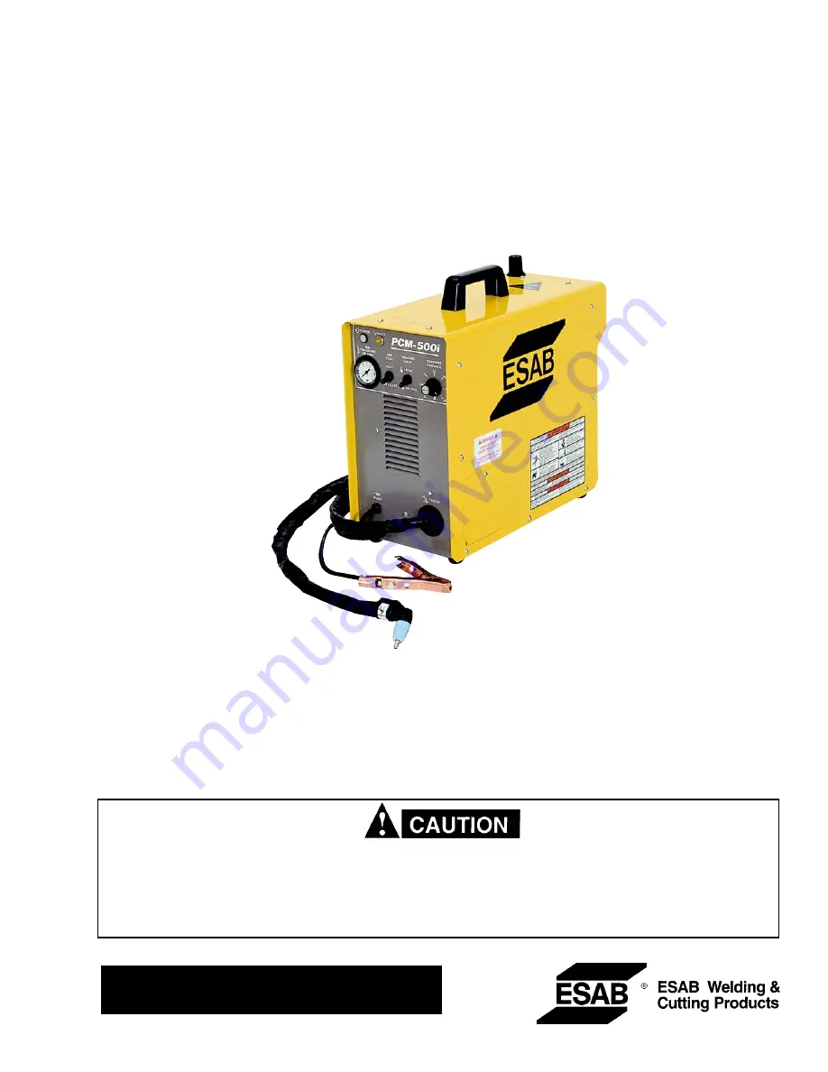
background image

INSTRUCTION MANUAL

PCM-500i

PLASMA ARC CUTTING PACKAGES

These INSTRUCTIONS are for experienced operators.  If you are not fully familiar with the principles of operation and
safe practices for arc welding equipment, we urge you to read our booklet, "Precautions and Safe Practices for Arc
Welding, Cutting, and Gouging," Form 52-529.  Do NOT permit untrained persons to install, operate, or maintain this
equipment.  Do NOT attempt to install or operate this equipment until you have read and fully understand these
instructions.  If you do not fully understand these instructions, contact your supplier for further information.  Be sure
to read the Safety Precautions  before installing or operating this equipment.

F-15-296-

E

 Feb.

, 200

4

This manual provides complete instructions for the following PCM-500i cutting packages starting with Serial No. PORI612001:

ESAB P/N 36314 - 208/230 V, 1-Phase, 50/60 Hz
ESAB P/N 36316 - 400 V (380/415 V), 3-Phase, 50/60 Hz

Be sure this information reaches the operator.
You can get extra copies through your supplier.

Summary of Contents for PCM-500i

Page 1: ...attempt to install or operate this equipment until you have read and fully understand these instructions If you do not fully understand these instructions contact your supplier for further information Be sure to read the Safety Precautions before installing or operating this equipment F 15 296 E Feb 2004 This manual provides complete instructions for the following PCM 500i cutting packages startin...

Page 2: ...ch results from improper use faulty maintenance damage improper repair or alteration by anyone other than the manufacturer or a service facility designated by the manufacturer TABLE OF CONTENTS SECTION TITLE PAGE PARAGRAPH SECTION 1 DESCRIPTION 7 1 1 General 7 1 2 Scope 7 1 3 Packages Available 7 1 4 Specifications 8 9 1 5 Optional Accessories 9 SECTION 2 INSTALLATION 10 2 1 General 10 2 2 Equipme...

Page 3: ...es on the workpiece which might pro duce flammable or toxic vapors Do not do hot work on closed containers They may explode 4 Have fire extinguishing equipment handy for instant use such as a garden hose water pail sand bucket or portable fire extinguisher Be sure you are trained in its use SAFETY PRECAUTIONS 10 98 5 Do not use equipment beyond its ratings For example overloaded welding cable can ...

Page 4: ... Never strike an arc on a cylinder 5 For additional information refer to CGA Standard P 1 Precautions for Safe Handling of Compressed Gases in Cylinders which is available from Compressed Gas Association 1235 Jefferson Davis Highway Arlington VA 22202 EQUIPMENT MAINTENANCE Faulty or improperly maintained equipment can cause injury or death Therefore 1 Always have qualified personnel perform the in...

Page 5: ...oigné de la zone de travail augmente en effet le risque de pas sage d un courant de sortie par des chaînes delevage PRÉCAUTIONS DE SÉCURITÉ AVERTISSEMENT Ces règles de sécurité ont pour objet d assurer votre protection Veillez à lire et à observer les précautions énoncées ci dessous avant de monter l équipement ou de commercer à l utiliser Tout défaut d observation de ces précautions risque d entr...

Page 6: ...ticulières en matière de ventilation indiquées à l alinéa 6 de la norme Z49 1 de l AWS 5 ENTRETIEN DE L ÉQUIPEMENT Un équipement entretenu de façon défectueuse ou inadéquate risque non seulement de réaliser un travail de mauvaise qualité mais chose plus grave encore d entraîner des dommages corporels graves voire mortels en déclenchant des incendies ou des chocs électriques Observez par conséquent...

Page 7: ...sed with any other torch 1 2 SCOPE Thepurposeofthismanualistoprovidetheoperatorwith all the information required to install and operate the PCM 500i plasma arc cutting package Technical refer ence material is also provided to assist in troubleshoot ing the cutting package 1 3 PACKAGES AVAILABLE Table 1 1 lists available PCM 500i packages Table 1 1 PCM 500i Cutting Packages Each PCM 500i Plasma Arc...

Page 8: ...8003301 includes 35 40 A Nozzle 20860 3 Electrode 20862 2 Swirl Baffle 20463 1 Heat Shield 20282 1 NOTE PT 31XL Torch Assembly P N 21985 is supplied with the nozzle electrode swirl baffle and heat shield assembled Rated Output 40 Duty Cycle 35 A 120 V dc 60 Duty Cycle 30 A 120 V dc 100 Duty Cycle 22 A 120 V dc Output Current Range 10 to 35 Amperes Open Circuit Voltage 265 V dc Nominal Rated Primar...

Page 9: ...rtsKitHolder P N33952GY Units now have 4 mounting holes on left side for mounting this accessory holder starting around Oc tober 1996 2 Wheel Cart P N 34324 This 5 7 8 high cart has front swivel casters and rear casters to make it easier to roll the PCM 500i around the job site 3 SparePartsKits P N19676 Recommendedwhen cutting below 20 amps See Section 3 3 and Figure 3 2A The kit includes 4 Heat S...

Page 10: ...onnect the input power cord directly to the disconnect switch or purchase a proper plug and receptacle from a local electrical supplier The cable connectingthedisconnectswitchtothereceptacleshould include four three power and one ground No 12 AWG insulated conductors 2 1 GENERAL Proper installation can contribute materially to the satis factory and trouble free operation of the PCM 500i cut ting p...

Page 11: ...ith a properly sized ground cable 2 6SECONDARY OUTPUT CONNECTIONS REFER TO FIG 2 1 Beforemakinganyconnectionstothepowersource output terminals make sure that all primary input powertothepowersourceisdeenergized off atthe main disconnect switch and that the input power cable is unplugged 1 For operator safety the torch connections are lo cated on the output terminal board behind the lower portion o...

Page 12: ...K CABLE SAFETY GROUND TORCH POWER CABLE CONNECTION PT 31XL WORK PLUG Equipped only on 230 V 1 phase units between work and power source Allow at least 10 ft 3 m ACCESS DOOR FOR TORCH CONNECTION NOTE If using 208 V input see Section 2 7 and Fig 2 2 RECEPTACLE P N 674540 Optional for 208 230 V 1 phase power sources TORCH SWITCH RECEPTACLE Prefiltered AIR SUPPLY Customer Supplied 90 to 150 psig max ...

Page 13: ...te the input bridge IBR and the two position terminal block on the left side of the unit towards the rear panel see Fig 1 Locate the gray wire con nected to TB5 2 and to IBR terminal R For 108 Vac input disconnect the gray wire from TB5 2 and then firmly connect it to TB5 1 3 Locate the output bridge D1 on the left side to wards the front panel see fig 2 Disconnect and swap leads X2 and X3 from th...

Page 14: ...ALLATION 14 Figure 2 3 Ground and Work Cable Connections GROUNDED WORK TABLE EARTH GROUND WORK CABLE BE SURE WORK IS IN GOOD CONTACT WITH TABLE WORK CABLE EARTH GROUND DO NOT ATTACH WORK CABLE TO PIECE BEING CUT FREE ...

Page 15: ...ER 3 2 PCM 500i CONTROLS FIGURE 3 1 A Power Switch located on rear panel When placed in ON position the white pilot light will glow indicating control circuit is energized and the cool ing fan will run B Output Current Control Adjustable from 10 to 35 amperes to suit cutting conditions C Air Check Switch When placed in ON position air filter regulator can be adjusted to desired pres sure 65 75psig...

Page 16: ...low amber under the following conditions and operations will come to a complete stop Flow Fault The fault light will be mostly on but will flick off for about 1 10th of a second every second This indicates that the air flow supply is low Over Temperature The fault light will be mostly off but will flick on for about 1 10th of a second every second This indicates that the duty cycle has been exceed...

Page 17: ...5 psi Output Cutting Thickness Current Speed Material In Amps ipm Carbon 1 16 30 180 Steel 1 8 30 75 AISI 1020 1 8 35 85 1 4 35 30 3 8 35 15 1 2 35 12 Stainless 1 16 30 200 Steel 1 8 30 85 AISI 304 1 8 35 85 1 4 35 30 3 8 35 14 1 2 35 10 Aluminum 1 16 30 200 6061 1 8 30 85 1 8 35 85 1 4 35 30 3 8 35 15 1 2 35 12 NOTE The speeds given here are typical for best quality cuts Your actual speeds may va...

Page 18: ...revent the possibility of welding the tip to the plate The torch should be angled at about 30 when starting to pierce and then straightened after accomplishing the pierce 2 Grate Cutting For rapid restarts such as grate or heavy mesh cutting do not release the torch switch Thisavoidsthe2secondpreflowportionofthecutting cycle 3 6 COMMON CUTTING PROBLEMS Listed below are common cutting problems foll...

Page 19: ...place if necessary E Make sure cable and hoses are not damaged or kinked F Make sure all fittings and ground connections are tight Wateroroiloccasionallyaccumulatesincompressed air lines Be sure to direct the first blast of air away from the equipment to avoid damage to the PCM 500i PISTON PLUG PISTON SPRING FLOW SWITCH H With all input power disconnected and wearing propereyeandfaceprotection blo...

Page 20: ...ected Opentheline wall disconnectswitch or circuit breaker before attempting inspection or work inside of the power source Check the problem against the symptoms in the follow ing troubleshooting guide The remedy may be quite simple If the cause cannot be quickly located shut off the input power open up the unit and perform a simple visual inspection of all the components and wiring Check for secu...

Page 21: ...es No Connect Is air adjusted to 65 75 psig Yes No Adjust Does air come on with air check switch Yes No No electrode in torch No valve pin in torch Replace electrode Check continuity of torch switch Replace valve pin OK No Replace torch switch Repair power source ...

Page 22: ...air check switch OFF Yes No Turn switch OFF Does arc start when nozzle contacts work without depressing torch switch Yes No Check for short in torch switch Does air flow even when PCM 500i power switch is OFF Yes No Replace Repair power solenoid valve source ...

Page 23: ...s main 230 volt switch ON Yes No Turn on main disconnect Is plug in receptacle Yes No Insert plug in receptacle Is cooling fan turning Yes No Replace pilot light Check voltage at receptacle and input power line Yes No Check main fuses Faulty power switch on PCM 500i ...

Page 24: ...ch OFF and then ON again NOTE When in LOCK IN mode the FAULT light will turn on during second trigger This does not affect performance Turn off E Amber FAULT light ON Is the unit overheated Fault lights turns off when Unit cools down Yes No Is air flowing Duty cycle exceeded 40 35 A 60 30 A Yes No or 100 22 A output See page 5 2 Is input voltage within 15 of units input rating Yes No Adjust voltag...

Page 25: ...e canceled and the HF is energized immediately 2 When the amber fault pilot light comes on cutting operation should be stopped The postflow time starts from the moment the torch switch is released TORCH SWITCH OPEN CLOSE GAS SOLENOID VALVE PREFLOW FLOW SWITCH CLOSE FAULT OVERLOAD LIGHT HF CIRCUIT INVERTER CUTTING ARC CURRENT 5 3 SEQUENCE OF OPERATION A LOCK IN OFF position ...

Page 26: ...ENT NOTES 1 When the torch switch is pushed during postflow period the postflow and preflow times are canceled and the HF is energized immediately 2 When the amber fault pilot light comes on cutting operation should be stopped The postflow time starts from the moment the torch switch is released 3 FAULT pilot light is on during second turn off trigger only This does not affect performance in any w...

Page 27: ...27 D 36338 E NOTE For 220 V 1 and 3 phase CE Units see Supplement F 15 395 Figure 5 1 Schematic Diagram PCM 500i 200 230 Vac 50 60 Hz 1 Phase ...

Page 28: ...28 D 36403 G Sheet 1 Figure 5 2 Wiring Diagram PCM 500i 200 230 Vac 50 60 Hz 1 Phase Sheet 1 ...

Page 29: ...29 D 36403 G Sheet 2 Figure 5 2 Wiring Diagram PCM 500i 200 230 Vac 50 60 Hz 1 Phase Sheet 2 ...

Page 30: ...30 D 36339 E Figure 5 3 Schematic Diagram PCM 500i 380 415 Vac 50 60 Hz 3 Phase ...

Page 31: ...31 D 36524 E Sheet 1 Figure 5 4 Wiring Diagram PCM 500i 380 415 Vac 50 60 Hz 3 Phase Sheet 1 ...

Page 32: ...32 D 36524 E Sheet 2 Figure 5 4 Wiring Diagram PCM 500i 380 415 Vac 50 60 Hz 3 Phase Sheet 2 ...

Page 33: ...ING To assure proper operation it is recommended that only genuine ESAB parts and products be used with this equipment The use of non ESAB parts may void your warranty Replacement parts may be ordered from your ESAB distributor or from ESAB Welding Cutting Products Attn Customer Service Dept PO Box 100545 Ebenezer Road Florence SC 29501 0545 Be sure to indicate any special shipping instructions wh...

Page 34: ...s included 7 1 634518 SWITCH TOGGLE DPDT 2POS 15A S1 8 1 951526 LAMP WHITE PL2 9 1 951754 LAMP YELLOW PL1 10 2 993426 GROMMET 1 5 ID 11 1 21711 GAUGE PRESSURE 12 1 673213 SWITCH TOGGLE SPST 2 POS 15A S2 13 1 23602576 STRAIN RELIEF 14 2 951474 SWITCH SEAL 15 4 182W12 FOOT 16 1 36330YL ACCESS DOOR ESAB 1 36330LG ACCESS DOOR L TEC 17 1 2091514 WARNING LABEL 18 2 13734588 LABEL ESAB 19 1 954008 WARNIN...

Page 35: ...SFORMER T2 37 1 951182 FAN AC AXIAL M1 38 1 21698 AIR LINE FILTER REGULATOR 39 1 35945 INDUCTOR POWER FACTOR CORRECTION 230V L2 40 1 92W57 GROMMET 63 ID 41 1 35941 MAIN TRANSFORMER T1 42 1 952606 INDUCTOR OUTPUT L1 43 1 680560 WORK CABLE 25 FT includes CLAMP 13730862 44 1 182W64 RECEPTACLE TWIST LOCK MIDGET J1 45 1 36333 OUTPUT TERMINAL BOARD 46 1 58V75 ADAPTOR B A 1 4 NPTM BULKHEAD 47 1 32969 REA...

Page 36: ...SECTION 6 REPLACEMENT PARTS 36 71 70 64 63 62 61 84 82 83 81 79 76 75 88 74 73 63 85 72 67 67 200 230 V 1 Phase Power Source illustrated 65 66 68 69 65 66 78 77 86 90 89 ...

Page 37: ...C 400 V C22 72 1 951028 CAPACITOR 1µf 630 VDC 230 V C3 2 951028 CAPACITOR 1µf 630 VDC 400 V C3 C15 73 1 951085 THERMAL SWITCH D T 176 15 A 120 V TS1 74 1 2062282 CAPACITOR 0 22µf 1KV C19 75 1 952149 MODULE INPUT BRIDGE 50 A includes PAD 951191 IBR 76 2 17750010 RESISTOR 50 W 10 OHM PAD 951194 R7 R10 77 1 32958 CURRENT TRANSFORMER T4 78 1 951161 CAPACITOR 20µf 400 VDC C4 79 1 17145339 RESISTOR 39 K...

Page 38: ...into 2 equal halves 110 1 952176 CIRCUIT BREAKER 40 A 208 230 v 1 ph CB1 1 952178 CIRCUIT BREAKER 15 A ALL 3 PH CB1 111 1 951470 CAPACITOR 0 047µf 300 VAC 208 230 V 1 PH C20 112 1 951321 VARISTOR METAL OXIDE 208 230 V 1 PH MOV1 113 1 952559 FUSE 3A 600VAC FAST ACTING F1 114 1 954555 LABEL RATING 208 230 V 1 PH ESAB 1 954616 LABEL RATING 400 V 3 PH ESAB 115 1 13734727 STRAIN RELIEF 116 1 34574 CABL...

Page 39: ...nductor 952002 for improved performance 5 Thermal Pads are now included with IBGT s and Bridge Modules 6 On the 208 230Vac units the Q1 and Q2 50A IGBT s 952148 was changed to 100A IGBT 951205 7 On the 208 230Vac units the 10 ft Input Power Cable 34574 was changed to 6 ft cable 36673 The C edition 1 02 of this manual covers the following changes 1 Wiring Diagram 36403 has been updated 2 Item 116 P...

Page 40: ... 5 00 PM EST Warranty Returns Authorized Repair Stations C TECHNICAL SERVICE Telephone 800 ESAB 123 Fax 843 664 4452 Part Numbers Technical Applications Hours 8 00 AM to 5 00 PM EST Performance Features Technical Specifications EquipmentRecommendations D LITERATURE REQUESTS Telephone 843 664 5501 Fax 843 664 5548 Hours 7 30 AM to 4 00 PM EST E WELDING EQUIPMENT REPAIRS Telephone 843 664 4469 Fax 8...

Reviews: