


Use and maintenance manual
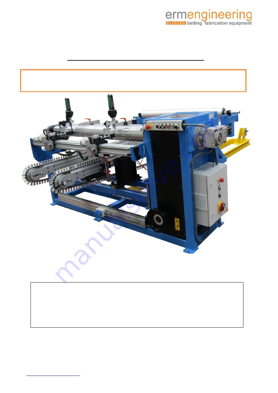
Sidewall and ropes welding machine
Model: LRBW-150
____________________________________________________________________________________________________________________
info@ermengineering
✆
(+34)937632525
P a g . 1
(Original) Use and maintenance manual
Type: Si V-Guide welder
Model: LRBW-150
IMPORTANT:
Read this user manual and follow the instructions and warnings before operating this device.
Any modification or transformation performed on this machine may cause loss of the
manufacturer’s guarantee and liability.
This manual must always remain near to the machine and visible to all the operating and
maintenance staff, for any future consultation, forming part of the equipment.


