ERMA SSI 1417, Instruction Manual
Download the free ERMA SSI 1417 Instruction Manual from our website. This comprehensive manual provides step-by-step instructions and essential information on operating and maintaining your ERMA SSI 1417. Easily accessible and user-friendly, our manual ensures a smooth experience with your product. Visit manualshive.com to get your download now!
Share
Download


Reviews:
No comments
Related manuals for SSI 1417

Gryphon GD4100
Brand: Datalogic Pages: 10
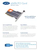
eSATA PCI Card
Brand: LaCie Pages: 2

AudioSystem EWS64L
Brand: TerraTec Pages: 2

BCM94312HMGB
Brand: Broadcom Pages: 39

LVDS 8R
Brand: Dynamic Engineering Pages: 46

N630GT series
Brand: MSI Pages: 1

GV-N94T-512H
Brand: Gigabyte Pages: 40

ADQ-610 cPCi
Brand: Alldaq Pages: 36

DV/AV 883
Brand: KWorld Pages: 21

10/100/1000Mbps PCI Adapter AGIGA32PCI
Brand: Airlink101 Pages: 4

AWLH3026
Brand: Airlink101 Pages: 31

EXA31
Brand: Nordic ID Pages: 16

SAMPO S2
Brand: Nordic ID Pages: 22

VX1950GT-512P
Brand: Diablotek Pages: 1

VX1950GT-512A
Brand: Diablotek Pages: 1

V9000-P128
Brand: Diablotek Pages: 1

PCI-1680U
Brand: Advantech Pages: 104

AVC05
Brand: V.TOP Pages: 9


