background image


BA46E033

Operating Instructions


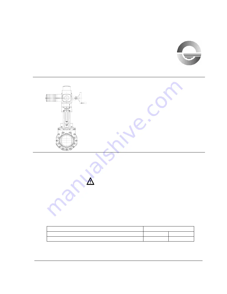
ERHARD ERU Knife Gate Valve K1 

DN 50 - 300 


Electric Actuator 


1 Safety 
2  Description of Product and Range of Application
3  Design Features – Technical Data    
4  Performance and Mode of Operation 
5 Storage 
6  Installation into the Pipeline - Mounting 
7 Initial 

Operation 

8 Operation 
9 Maintenance 


These operating instructions must always be used in combination with operating 
instructions BA01E001!


1 Safety 


Access to the range of movement of the gate of ERU Knife Gate Valves with electric 
actuator has to be restricted by protective devices. Effective protective devices have to 
be installed by the user.


On request, we will supply suitable protective guards. 


Description of Product and Range of Application 
 

Type/Design Product 

Number 

ERU Knife Gate Valve K1 

4657     

PN 10 

ERU Knife Gate Valve K1 with regulating orifice 

4623     

PN 10 


Design with electric actuator 

BA46E033 
July 2005 
Rev. 4 

ERHARD-Armaturen 

x

 D-89502 Heidenheim 

x

 Postfach 1280 

 (07321) 320-0  

 (07321) 320 491  e-mail:info

@

erhard.de  

Internet: http://www.erhard.de 

Page 1 of 13 


Summary of Contents for ERU K1

Page 1: ...fety Access to the range of movement of the gate of ERU Knife Gate Valves with electric actuator has to be restricted by protective devices Effective protective devices have to be installed by the user On request we will supply suitable protective guards 2 Description of Product and Range of Application Type Design Product Number ERU Knife Gate Valve K1 4657 PN 10 ERU Knife Gate Valve K1 with regu...

Page 2: ...ls are used for the ERU Knife Gate Valves K1 the parts of EPDM must not get in contact with oil or grease as the EPDM would swell For a recommended lubricant see section Maintenance ERU Knife Gate Valves K1 of this design are suitable for ON OFF operation For explicit regulating service special designs have to be used e g design with regulating orifice BA46E033 July 2005 Rev 4 ERHARD Armaturen x D...

Page 3: ...uator 3 Design Features Technical Data Drawing 2E 39861 ERU Knife Gate Valve K1 with electric actuator BA46E033 July 2005 Rev 4 ERHARD Armaturen x D 89502 Heidenheim x Postfach 1280 07321 320 0 07321 320 491 e mail info erhard de Internet http www erhard de Page 3 of 13 ...

Page 4: ...861 1 PREFERRED SERIES FOR MODULATING ACTUATORS PREFERRED SERIES FOR STANDARD ACTUATORS 3 EN558 1 BASIC SERIES 20 FORMER DIN 3202 PART 3 SERIES K1 BA46E033 July 2005 Rev 4 ERHARD Armaturen x D 89502 Heidenheim x Postfach 1280 07321 320 0 07321 320 491 e mail info erhard de Internet http www erhard de Page 4 of 13 ...

Page 5: ... element X 3 Hexagon bolt 4 Washer 5 Hexagon nut 6 Gate 7 Profile seal X X 8 Guide tape X X 9 Compressor 10 Taper plug 11 Cover plate 12 Washer 13 Hexagon bolt 14 Bush 15 Fork nut X X 16 Bolt 17 Washer 18 Cotter pin 19 Stem X 20 Straight grooved pin 21 Stud bolt 22 Gudgeon 23 Bearing support 24 Washer 25 Hexagon nut 26 Electric multi turn actuator 27 Washer 28 Cylindrical screw 29 Taper plug BA46E...

Page 6: ...gnalled by the travel switches Running against or jamming at the upper mechanical stop of the valve due to motor after running is avoided The torque switches serve as safety switches in opening and closing directions ERU Knife Gate Valves K1 are switched in a travel dependent manner in closing and opening directions 4 1 Retrofitting of an Electric Multi Turn Actuator If the valve is supplied witho...

Page 7: ...l position 4 2 2 Check the gate movement and thus the direction of rotation of the actuator by short electrical starting Valve is closing CLOCKWISE direction of actuator rotation Valve is opening ANTI CLOCKWISE direction of actuator rotation 4 2 3 In case of wrong direction of rotation change poles of motor connection 4 2 4 Check direction of rotation by short electrical starting 4 2 5 Check corre...

Page 8: ...e moved in the opposite direction until the torque switch completley returns to its original position Only now the valve may be moved again in the direction in which the disturbance occurred Proceeding this way you will obtain torques corresponding to the torques set at the torque switch Moreover the foreign matter can come off and be flushed out of the seating zone Operation by emergency handwhee...

Page 9: ...case of deviating installation positions especially with suspended stem or piston rod deposits around the gate have to be expected This could lead to mal functions which increase maintenance work During installation of the valve the distance between the pipe flanges should exceed the valve face to face dimension by at least 20 mm Thus the raised faces will not be damaged and the gaskets can be ins...

Page 10: ... of bolts in the through going holes For the threaded blind holes the screwed connection is made by means of stud bolts or bolts in the body components It is possible to roughly fasten the valve by means of the threaded holes The necessary connecting elements for the corresponding installation position are shown in drawing No 4E127 920 BA46E033 July 2005 Rev 4 ERHARD Armaturen x D 89502 Heidenheim...

Page 11: ...with electric actuator Connecting elements for flange connection to drawing 4E127920 BA46E033 July 2005 Rev 4 ERHARD Armaturen x D 89502 Heidenheim x Postfach 1280 07321 320 0 07321 320 491 e mail info erhard de Internet http www erhard de Page 11 of 13 ...

Page 12: ...Maintenance Wearing of the profile seal Replace profile seal Contamination deposit on the gate With valve in open position clean and grease gate Seat leakage Contamination of the gate With valve in open position clean and grease gate Defective U shaped sealing element Replace sealing element Excessive operating forces Contamination deposit on the gate With valve in open position clean and grease g...

Page 13: ...epending on the flow medium and the local conditions at the site of application the maintenance interval must be reduced or may be extended If the profile seal is found to be untight retighten the hexagon bolts of the cover plate evenly If it is no longer possible to retighten the cover plate replace the sealing elements Check gate and stem regularly for contaminations clean them if necessary and ...

Reviews: