background image

Epson

®

 Progression™ User’s Guide

Update

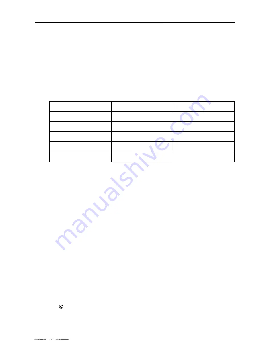
Please note that the memory configuration table shown on

pages 3-12 and 

3-13 

of your 

User’s Guide 

is incorrect. Please

replace it with the following table.

SIMM configuration

Socket U11 Socket U12 Total memory

4MB*

1MB 1MB 6MB

4MB 4MB 12MB

14MB 16MB 36MB

64MB** 64MB** 128 MB t

* Standard soldered memory

** Check with your dealer to see if this SIMM is available

t With this memory configuration, the 4MB of soldered memory is disabled-

Epson is a registered trademark and Progression is a trademark of Seiko Epson
Corporation.

Copyright   1992 by Epson America, Inc.
Torrance, California 

 400183400

Summary of Contents for Progression

Page 1: ...ocket U11 Socket U12 Total memory 4MB 1MB 1MB 6MB 4MB 4MB 12MB 14MB 16MB 36MB 64MB 64MB 128 MB t Standard soldered memory Check with your dealer to see if this SIMM is available t With this memory configuration the 4MB of soldered memory is disabled Epson is a registered trademark and Progression is a trademark of Seiko Epson Corporation Copyright 0 1992 by Epson America Inc Torrance California m0...

Page 2: ...EPSON PROGRESSION User s Guide l is manual is printed on recycled paper and is 100 recyclable ...

Page 3: ...nto an outlet on a circuit different from that to which the receiver is connected 0 Consult the dealer or an experienced radio TV technician for help WARNING The connection of a non shielded equipment interface cable to this equipment will invalidate the FCC Certification of this device and may cause interference levels that exceed the limits established by the KC for this equipment It is the resp...

Page 4: ...rm or by any means electronic mechanical photocopying recording or otherwise without the prior written permission of Epson America Inc No patent liability is assumed with respect to the use of information contained herein Nor is any liability assumed for damages resulting from the use of the information contained herein Further this publication and features described herein are subject to change w...

Page 5: ...uter using the type of power source indicated on its label If you are not sure of the type of power available consult your dealer or local power company 8 If you plan to operate the computer in Germany observe the following safety precaution To provide adequate short circuit protection and overcurrent protection for this computer the building installation must be protected by a 16 Amp circuit brea...

Page 6: ...icing to qualified service personnel 14 Unplug the computer from the wall outlet and refer servicing to qualified service personal under the following conditions A When the power cord or plug is damaged B If liquid has entered the computer C If the computer does not operate normally when the operating instructions are followed Adjust only those controls that are covered by the operating instructio...

Page 7: ...source de chaleur dire e Le fonctionnement de l ordinateur doit s effectuer conformement au type de source d aiimentation indiqu e sur l etiquette Dans le cas d un doute de la source disponible on doit communiquer avec le concessionaire ou la compagnie d ctriciM Lorsqu on desire utiliser l ordinateur en Allemagne on doit observer les normes s uitaires qui suivent Afin d assurer une protection adeq...

Page 8: ...ervice de cet appareil a un technicien qualifie 14 Debrancher l ordinateur de la prise murale et confier le service au personnel de service qualifie selon les conditions qui suivent A Lorsque le cordon d alimentation ou la prise sont endommagk B Lorsqu un liquide s est infib dans l ordinateur C Lorsque I ordinateur refuse de fonctionner normalement meme en suivant les instructions N ajuster que le...

Page 9: ...Using Disks and Disk Drives 1 5 How Disks Store Data 1 6 Types of Diskette Drives 1 7 Caring for Diskettes and Diskette Drives 1 10 Write protecting Diskettes 1 12 Inserting and Removing Diskettes 1 14 Using a Single Diskette Drive System 1 16 Formatting Diskettes 1 17 Making Backup Copies 1 17 Using a Hard Disk Drive 1 18 Special Keys on the Keyboard 1 20 Stopping a Command or Program 1 21 Resett...

Page 10: ...7 Chapter 2 Accessing Internal Components Special Precautions 2 2 Removing the Cover 2 3 Removing the Front Panel 2 5 Removing the Subassembly 2 7 Replacing the Subassembly 2 9 Replacing the Front Panel 2 11 Replacing the Cover 2 12 Chapter 3 Installing and Removing Options Main System Board Map 3 3 Jumper Settings 3 4 Setting the Jumpers 3 5 Option Cards 3 6 Installing an Option Card 3 8 Removing...

Page 11: ... 4 3 Checking the IDE Hard Disk Drive Jumpers 4 4 Where to Go Next 4 5 Installing a Drive in the External Bay 4 6 Connecting the Cables 4 9 Removing a Drive From the External Bay 4 14 Installing a Hard Disk Drive in the Internal Bay 4 16 connecting the Cables 4 20 Removing a Hard Disk Drive From the Internal Bay 4 25 Post installation Procedures 4 27 Chapter 5 Running System Diagnostics Starting t...

Page 12: ... 7 Troubleshooting Identifying Your System 7 1 Error Messages 7 2 The Computer Won t Start 7 5 The Computer Does Not Respond 7 6 Restoring the Power Supply 7 8 Password Problems 7 9 Accessing Your System 7 10 Keyboard Problems 7 11 Monitor Problems 7 12 Diskette Problems 7 13 Diskette Drive Problems 7 15 Hard Disk Problems 7 16 Installing the Drive 7 17 Preparing the Drive 7 18 Accessing Data on t...

Page 13: ...A 1 Controllers A 4 Interfaces A 4 Mass Storage A 5 Keyboard A 5 Power Supply A 4 Environmental Requirements A 7 Physical Characteristics A 7 Power Source Requirements A 8 System Memory Map A 9 Extended VGA modes A 10 Wingine Modes A 11 Index ...

Page 14: ...ystem memory as a virtual cache pool Integrated VGA video graphics array controller with Wingine video technology developed by Chips and Technologies for Microsoft Windows users Built in serial and parallel ports Built in IBM PS 2 compatible keyboard and mouse ports Six 16 bit option slots Support for up to five mass storage drives two internal and three externally accessible Upgradable CPU centra...

Page 15: ...uffer which typically fills up with the first or second memory access command your computer uses all the RAM as a virtual cache buffer You ll notice the improved performance especially when running memory consuming graphics programs such as Windows applications or draw programs Using the built in interfaces you can connect your peripheral devices directly to the computer so you don t have to insta...

Page 16: ...peeds up your video performance to match the capability of your CPU card OverDrive Module You can also enhance your system without replacing the CPU card by installing an Intel OverDrive module on the CPU card This doubles the internal clock speed of the microprocessor so your system runs much faster Math Coprocessor You may want to install a math coprocessor to enhance the speed and performance o...

Page 17: ...stead of just 16 or 256 Check with your authorized Epson dealer for information on optional equipment For installation instructions see Chapters 2 3 and 4 of this manual VGA Utilities Your computer comes with special MS DOS VGA device drivers and utilities for use with the integrated VGA interface With these utilities you can take advantage of extended VGA features such as high resolutions and 132...

Page 18: ...omponents inside the computer Chapter 3 describes how to change jumper settings and install optional equipment such as option cards memory modules a CPU card an OverDrive module a math coprocessor and a video daughter board Chapter 4 explains how to install and remove disk drives Chapter 5 provides instructions for running system diagnostics Chapter 6 gives the procedure for formatting a hard disk...

Page 19: ...es parts documentation and accessories for your Epson product Customer Relations Epson technical information library fax service also available directly by calling the toll number 310 782 4214 Product literature with technical specifications on our current and new products User group information If you purchased your computer outside the United States please contact your dealer or the marketing lo...

Page 20: ...skettes and disk drives and reset the computer If you are familiar with these aspects of operating a computer you may want to skip the first few sections of this chapter However be sure to read the later sections which describe system operations specific to your computer such as using a password changing the processor speed and preparing the hard disk for moving Using Your Computer 1 1 ...

Page 21: ...ays wait at least 10 seconds after you turn off the power before you turn it on again This prevents possible damage to the computer s electrical circuitry Follow these steps to turn on your system 1 Turn on the monitor printer and any other peripheral devices connected to the computer 2 If you do not have a hard disk or if you have not installed the operating system on the hard disk insert your ma...

Page 22: ...a series of checks the computer runs each time you turn it on to make sure everything is working correctly If necessary use the controls on your monitor to adjust the screen display Note If you or your dealer has made a major change to your system such as adding a disk drive you may need to wait a few minutes for your computer to complete power on diagnostics the first time you turn it on When the...

Page 23: ...our operating system manuals for installation instructions What happens next depends on how your computer is set up If it is configured to automatically load a program such as Windows or a word processing program you see the first menu or screen display of that program If not you may see the operating system prompt such as C B or A See your application program manuals for further instructions Turn...

Page 24: ...n If you move your computer before this happens you could damage your hard disk drives Using Disks and Disk Drives The disk drives in your computer allow you to store data on disk and then retrieve and use your stored data This section explains how disks work and tells you how to Cl Use different types of diskettes and diskette drives Q Care for your diskettes and diskette drives 0 Write protect d...

Page 25: ...f dust and dirt A hard disk stores data the same way that a diskette does but it works much faster and has a much larger storage capacity All disks are divided into data storage compartments by sides tracks and sectors Double sided diskettes store data on both sides On each side are concentric rings called tracks on which a disk can store data A disk is further divided by sectors which can be visu...

Page 26: ...under the read write head where the data is to be written A diskette has an exposed area where the read write head can access it Because data is stored magnetically you can retrieve it record over it and erase it just as you play record and erase music on a cassette tape Types of Diskette Drives The following list describes the four types of diskette drives you can use in your computer and which d...

Page 27: ...er track With 8 sectors per track a diskette holds up to 320KB With 9 sectors per track a diskette holds up to 360KB of information approximately 150 pages of text Note You must format a new diskette before you can store data on it See Formatting Diskettes later in this section Drive and diskette incompatibilities If your computer has more than one type of diskette drive or if you use different ty...

Page 28: ...te If you want to format a 720KB diskette in a 1 44MB drive or format a 360KB diskette in a 1 2MB drive make sure you include the correct parameter in your format command See your operating system manuals for instructions If you have any combination of the above drives 1 44MB 1 2MB 720KB or 360KB and you are using MS DOS you can copy files from one drive to another using COPY or XCOPY as long as t...

Page 29: ... drive or reset or turn off the computer while the drive light is on This light indicates that the computer is copying data to or from a diskette If you interrupt this process you can destroy data Keep diskettes in a moderate environment Don t leave them sitting in the sun or in extreme cold or heat because this can destroy the data P Keep diskettes away from dust and dirt Small particles of dust ...

Page 30: ...ou need to write on a label that is already on the diskette use only a soft tip pen not a ballpoint pen or a pencil 0 Carefully label your diskettes and indicate the type and density Do not stick several labels on top of one another this can make it difficult to insert and remove the diskette in the drive Store diskettes in their protective envelopes and in a proper location such as a diskette con...

Page 31: ...rom it but you cannot store new data on it or delete any files it contains To write protect a 5 25 inch diskette cover the small rectangular notch shown below with an adhesive write protect tab Write protect tabs usually are included in a new package of blank 5 25 inch diskettes To remove the write protection peel off the write protect tab 1 12 Using Your Computer ...

Page 32: ...o write protect a 3 5 inch diskette slide the switch toward the edge of the diskette until it clicks into position exposing a hole in the comer switch To remove the write protection slide the switch toward the center of the diskette until it clicks into position and the hole is covered or switch so they are Using Your Computer 1 13 ...

Page 33: ...way into the slot Then turn the latch down to lock it in a vertical position This keeps the diskette in place and enables the read write heads in the drive to access the diskette When you want to remove a diskette first make sure the disk drive light is off Then flip up the latch and carefully pull out the diskette Place it in its protective envelope and store it in a proper location such as a dis...

Page 34: ...until it clicks into place release button metal shutter When you want to remove the diskette make sure the drive light is off then press the release button When the diskette pops out remove it and store it properly Never remove a diskette or reset or turn off the computer on You could lose data Also remove all diskettes before you turn off the computer Using Your Computer 1 15 ...

Page 35: ... you may often swap diskettes this way it is important to remember which diskette is which It is also a good idea to write protect your original diskette See Write protecting Diskettes above If you have a hard disk and one diskette drive you can load the operating system and application programs from the hard disk create and store your data there and use the diskette drive just for copying data to...

Page 36: ...manuals for instructions on formatting diskettes Making Backup Copies It is important to make copies of all your data and system diskettes Make backup or working copies of all diskettes that contain programs such as your operating system Reference and Utility diskettes then use only the copies Store the original diskettes away from your working diskettes Also copy your data diskettes regularly whe...

Page 37: ...age capacity makes it easy to move back and forth between different programs and data files However because it is so easy to add programs and files to your hard disk you may find yourself trying to organize hundreds of files Most operating systems let you keep related files together in directories and subdirectories so they are easy to find and use See your operating system manuals for instruction...

Page 38: ...k Follow these precautions to protect your hard disk drive from damage and to avoid losing data Q Never turn off or reset the computer when the hard disk access light is on This light indicates that the computer is copying data to or from the hard disk If you interrupt this process you can lose data See the illustration on page 1 3 to locate the hard disk access light Ct Never attempt to open the ...

Page 39: ...d and the symbol keys in the main part of the keyboard are not affected Produces uppercase characters or the top symbols on the keys when used with the main character keys Produces lowercase characters when the Caps Lock function is on Works with other keys to perform special control functions Works with other keys to enter alternate character codes or functions Moves the cursor back one space del...

Page 40: ...toggles press the key once to turn on a function and again to turn it off When the function is enabled the corresponding light in the upper right comer of the keyboard is lit Stopping a Command or Program You may sometimes need to stop a command or program while it is running If you have entered an MS DOS or application program command that you want to stop try one of the following Q Hold down i a...

Page 41: ...lassify and store new data when you exit them in the normal manner If you reset the computer without properly exiting a program you may lose data To reset the computer the operating system must be either on the hard disk or on a diskette in drive A so if you do not have a hard disk insert a system diskette in drive A There are two ways to reset the computer 0 If you are using MS DOS hold down m an...

Page 42: ...If you do not have a hard disk insert a system diskette in drive A Then turn on the computer locking the Computer s Cover You can lock the cover onto the computer to prevent unauthorized users from accessing its internal components To lock the cover insert the key as shown on the left and turn it clockwise To unlock the cover insert the key as shown on the right and turn it counterclockwise Using ...

Page 43: ...characters you type Then press m You have three chances to enter the correct password The number that appears before the key prompt indicates how many tries you have left After the third incorrect try the screen displays a zero the keyboard locks up and you cannot use the computer Press the RESET button and try to enter the correct password again Note If you do not know the correct password see Pa...

Page 44: ...he computer At the key prompt enter your current password followed by a forward slash and the new one you want to use For example if your current password is 123 and you want to change it to ABC type 123 ABC The screen does not display what you type Do not use characters requiring the m key such as or in your new password The computer does not distinguish between characters that are produced with ...

Page 45: ...r current password followed by a forward slash For example if your password is 123 type 123 3 Press m A happy face character appears and then the computer loads the operating system The next time you turn on or reset the computer it does not request a password and loads the operating system immediately Note You can also delete your password using the SETUP program See Chapter 2 of the Setup Guide ...

Page 46: ...gram If you set a password but did not turn on network server mode you enter the password before the computer loads the operating system or the network software Once you load it anyone can access your system by typing commands on the keyboard However if you set a password and turn on network server mode you can load your operating system or network software before you enter the password This allow...

Page 47: ...omputer from a diskette in drive A however you see the password key prompt before the computer loads your operating system or network software Follow the instructions in Using a Password on page 1 24 to enter your password in this situation Follow these steps to enter your password 1 Turn on or reset your computer You do not see the key prompt h even though the computer is now waiting for you to e...

Page 48: ...eed which switches your computer s processor from high to low speed when it accesses a diskette drive Note When your computer is operating at high speed the TURBO light on the front panel is lit It is off when the computer is operating at low speed You should use high speed for almost everything you do because your programs will work faster However certain application programs have specific timing...

Page 49: ...gram that can run only on a diskette or that requires a key disk try to load the program at high speed If this works you do not need to set the speed to change automatically If you can t load the program on high set the speed to change automatically 0 If you are using a copy protected program that does not require a key disk but requires a special procedure to install it on a hard disk set the spe...

Page 50: ...board Commands You can change the processor speed temporarily by entering a command from your keyboard You can use these commands only if you have enabled the Software speed change option in the SETUP program Enabled is the default setting If this option is disabled you cannot use the keyboard commands The keyboard speed setting commands are listed in the table below Speed setting commands Numeric...

Page 51: ...SET button Q Turn off the computer Cl Change it using the SETUP program P Change it with another keyboard command P Change it using ESPEED Using the ESPEED Program ESPEED provides an easy way to change the processor speed if your application program does not recognize the cbll key commands or if you want to include the program command in a batch file The ESPEED program is on the Reference diskette...

Page 52: ... the ESPEED command again and include the appropriate switch such as the following ESPEED A This command sets the processor speed to change to low speed automatically when the computer accesses a diskette If you include the switch when you type the initial ESPEED command the program changes the speed without displaying the command options The processor speed you set remains in effect until you cha...

Page 53: ...nd starts the program Changing the Speaker Volume Your computer contains a built in speaker that beeps when you perform certain operations You can control the operation and volume of this speaker using the SETUP program and the SETVOL utility described below To enable or disable your speaker run the SETUP program and change the setting of the Speaker option as described in Chapter 2 of the Setup G...

Page 54: ...cally displays the volume setting as you increase or decrease it To decrease the volume press tl l T 1 or 1 To increase the volume press t 7 or r 7 You can use the keys on the main keyboard or the numeric keypad As you change the volume the speaker beeps so you can test the volume of the current setting 4 After you have selected the volume you want press Enl l to store the current setting and exit...

Page 55: ...e sure to include the slash in the parameter Preparing the Hard Disk for Moving If you need to move your computer to a new location you may want to run the HDSIT program provided on your Reference diskette to protect the hard disk during the move HDSIT moves or parks the disk drive s read write heads to a region on the disk surface that does not contain data and locks them securely in position Thi...

Page 56: ... allows your hard disk drive s read write heads to move away from the disk to a safe location If you move your computer before this happens you could damage your hard disk drives Using AUTOEXEC BAT and Other Batch Files If you are using MS DOS to access your application programs you may find that there are commands you need to run frequently You can automate the execution of these commands by list...

Page 57: ...MS DOS it creates an AUTOEXEC BAT file for you which you can modify or replace as described above Be sure to name the file AUTOEXEC BAT and store it in the root directory of the hard disk or diskette from which you load MS DOS You may want to rename your original file to AUTOEXEC OLD in case you need to use it again later See your MS DOS manuals for more information about creating and using batch ...

Page 58: ... remove the front panel and the subassembly the metal case that holds the drive bays The instructions in this chapter explain how to do the following 0 Remove and replace the cover P Remove and replace the front panel Q Remove and replace the subassembly Read the safety precautions on the next page before you begin Accessing Internal Components 2 1 ...

Page 59: ... the metal inside of the computer s back panel before you touch any components inside If you are not properly grounded you could conduct static electricity and damage your equipment When disconnecting a cable from any internal device such as a disk drive avoid pulling on the cable grasp the plastic connector to remove it from the socket When plugging a connector or a component into a socket be sur...

Page 60: ...oard Ll Install or remove disk drives or other storage devices Follow these steps to remove the cover 1 2 3 Turn off the computer and any peripheral devices connected to it Then disconnect the computer s power cord from the electrical outlet and from the back panel Also disconnect any peripheral device cables that are connected to the computer including the keyboard cable Turn the computer around ...

Page 61: ...g them counterclockwise as shown below The screws disengage but don t come all the way off 5 Grasp the sides of the cover toward the front of the computer and pull it firmly toward you as shown below Then lift it up and off the computer 2 4 Accessing Internal Components ...

Page 62: ... subassembly from the computer If you are installing an internal option you do not need to remove the front panel Follow these steps 1 Turn the computer so you are facing the front panel 2 Release the six tabs securing the front panel to the computer case as shown below You may want to use a flat blade screwdriver to release the tabs Accessing internal Components 2 5 ...

Page 63: ...t straight toward you to disengage the two tabs at the bottom as shown below Be careful not to pull the panel off at an angle this may bend or pop off the power and RESET buttons If a button pops off carefully place it back on to its post 2 6 Accessing Internal Components ...

Page 64: ...r 4 if you are not sure if you need to remove the subassembly Follow these steps 1 Turn the computer so you are facing the front panel 2 Disconnect the power supply and drive cables from the backs of all the drives installed in your computer as shown below Note which cables are connected to which drives so you can easily reconnect them later power supply drive cable Accessing Internal Components 2...

Page 65: ... the subassembly as shown below Then remove all the cables from the clasps Do not disconnect any cables from the main system board 4 Grasp the back of the subassembly by the edge on its upper left side as shown below and lift up the back end 2 8 Accessing Internal Components ...

Page 66: ...y Follow these steps to replace the subassembly 1 Turn the computer so you are facing the front panel 2 Hold the subassembly at a slight angle and guide the front of it down through the opening in the front of the computer as shown below 3 Fit the two holes in the lower front of the subassembly over the two posts on the front of the computer case as shown above Accessing Internal Components 2 9 ...

Page 67: ...st beneath the back right edge of the subassembly into the hole on the top of the power supply Then lower the subassembly all the way down 5 Gather the power supply and drive cables in the clasps on the side of the subassembly then shut the clasps 2 10 Accessing Internal Components ...

Page 68: ...uter s front panel 1 Turn the computer so you are facing the front 2 Align the openings in the front panel with the power and RESET buttons and any drives that extend out from the front of the computer case Also align the front panel tabs with the corresponding notches in the case Then guide the front panel straight onto the case as shown below 3 Press the front panel onto the computer to fully in...

Page 69: ...Slide the cover forward until the front edge overlaps the top edge of the front panel 4 Tighten the three thumbscrews on the back panel to secure the cover to the computer 5 Lock the cover onto the computer if desired See Chapter 1 for instructions 6 Reconnect your monitor printer keyboard and any other peripheral devices you have Then reconnect the power cord to the back of the computer and to an...

Page 70: ... of your computer by adding a variety of options or upgrading your system components including the following D Option cards LJ Memory modules cl Upgraded CPU card P Intel OverDrive module cl Math coprocessor cl Enhanced video daughterboard Installing and Removing Options 3 1 ...

Page 71: ...puter On the next page you ll find an illustration of your main system board which shows the location of any components you may need to locate All the instructions in this chapter assume you have removed the computer s cover if not see Chapter 2 for the procedure When you finish everything you need to do inside the computer return to Chapter 2 for instructions on replacing the cover 3 2 installing...

Page 72: ...ry components on your main system board SIMM sockets option slots VGA monitor port keyboard port I I serial larallel port Pop I mouse port I VI O daughterboard connectors power SUPPlY connectors I I JP3 IPA I VGA feature hard disk connector CPU card connector drive connector blskette dr ve connector Installing and Removing Options 3 3 ...

Page 73: ...le or disable an external mouse port 0 Set your monitor type to monochrome or color 0 Enable or disable the power on password function Ll Enable or disable the built in VGA display adapter If you need to change any jumper settings or if you want to check the current settings follow the instructions in this section Refer to the Main System Board Map on page 3 3 to locate the jumpers The following t...

Page 74: ...n VGA display adapter Disables the built in VGA display adapter so you can use a display adapter on an option card l Factory setting Setting the Jumpers If you need to change any jumper settings on the main system board follow these steps 1 Refer to the table above to identify which jumper setting s you need to change See the Main System Board Map on page 3 3 to locate the jumpers 2 A jumper s set...

Page 75: ... port Your computer has six 16 bit option slots each of which can accommodate an option card You can buy option cards from authorized Epson dealers as well as other vendors Before you install an option card check the power requirements given in the card s documentation Make sure that the power required by the card does not exceed the power limit for its slot and that the total power for all the ca...

Page 76: ...You can install either 8 bit or 16 bit option cards in these slots As you can see below a 16 bit card has an extra connector along the bottom 8 bit card Usually it does not matter which slot an option card occupies as long as it fits in the slot However you must follow these guidelines when deciding which slot to use CI You cannot install an 8 bit card that has an additional tab along the bottom P...

Page 77: ...play adapter card you may need to change the settings of jumpers JP5 and JP7 See page 3 4 for instructions 2 Remove the retaining screw from the top of the metal option slot cover hold on to the screw so it doesn t fall into the computer Then lift out the slot cover Keep the screw to secure the option card to the computer Store the slot cover in a safe place in case you remove the option card late...

Page 78: ...terials in case you remove the card later Adjust any switches or jumpers on the card if necessary Check the option card instructions 4 Holding the card by the top comers position it over the slot as shown below Insert the card into the slot guiding it straight down If the card does not go in smoothly do not force it pull it all the way out and try again keeping it straight as you insert it Examine...

Page 79: ...fore you start using the option If you installed a card with an additional interface you may need to run SETUP to change one of the computer s built in interface settings See Chapter 2 of the Setup Guide for instructions Removing an Option Card If you need to remove an option card follow these steps 1 Remove the screw securing the card to the back of the computer and pull it straight up and out of...

Page 80: ... memory soldered onto the main system board By installing memory modules also called SIMMs single inline memory modules you can increase the amount of memory in your computer up to 128MB Caution It is best to have your dealer install memory modules for you because they can be damaged easily if installed incorrectly If you prefer to install them yourself carefully follow all the instructions in thi...

Page 81: ...nger on one side which prevents them from fitting inside the socket correctly There are two SIMM sockets on the main system board and each can contain one memory module You can install SIMMs with a capacity of 1MB 4MB 16MB or 64MB The following table shows the possible SIMM configurations do not install memory in any other configuration Remember that there is already 4MB of memory soldered onto th...

Page 82: ...er to see If this SIMM Is available t With this memory configuration the 4MB of soldered memory Is disabled Once you have the SIMMs you need you or your dealer can install them in your computer If you want to install them yourself follow the instructions below Installing and Removing Options 3 13 ...

Page 83: ...oard toward the middle 2 If you are installing two SIMMs it is easiest to install the first SIMM in the left socket labelled U12 first Position it at an angle as shown below with the components facing toward the option slots Make sure you orient the SIMM in the correct direction before you push it into the socket 3 14 Installing and Removing Options ...

Page 84: ...ly do not force it pull it all the way out and try again Make sure the SIMM is fully inserted into the socket and that the pins on the retaining posts extend through the holes in both ends 4 If you are installing a second SIMM repeat steps 2 and 3 to install it in the other socket 5 After you replace the computer s cover be sure to run the SETUP program so your system can update its configuration ...

Page 85: ...the SIMM at each end Be careful not to pull the tabs too far or they may break tabs As you pull away the tabs the SIMM falls to the right at an angle Release the tabs and lift the SIMM out of the socket 2 If you are removing a second SIMM repeat the procedure described above 3 After you replace the computer s cover be sure to run the SETUP program so your computer can update its configuration See ...

Page 86: ...g the CPU card with a faster one There are three cards available for your computer cl 486SX 25 0 486DX 33 Q 486DX2 66 The instructions in this section describe how to remove the card installed in your computer and install a new one You also need to perform these procedures if you want to install an OverDrive module or a math coprocessor on the CPU card Installing and Removing Options 3 17 ...

Page 87: ...l the card straight up and out of its socket as shown above 3 If you are installing a new CPU card follow the instructions on the next page If you are installing a math coprocessor or OverDrive module see the appropriate section later in this chapter for instructions When you are ready to reinstall the CPU card return to page 3 19 for instructions 3 18 installing and Removing Options ...

Page 88: ...or 486DX 33 card read Checking the jumper settings below Checking the jumper settings There are jumpers on the 486SX 25 card and the 486DX 33 card that indicate what type of card it is These jumpers are set to the correct position at the factory but it is a good idea to check the settings to make sure they are correct Also if you install an OverDrive module on the 486DX 33 card you need to change ...

Page 89: ...to make sure the jumpers are set correctly before you install the card in your computer and change them if necessary 486SX 33 CPU card jumpers Jumper setting CPU card configuration W1 W2 W3 Card only no OverDrive module A A A ODP486DX 33 module installed For general information on setting jumpers see Jumper Settings on page 3 4 3 20 Installing and Removing Options ...

Page 90: ... Guide the card straight into the socket until it is firmly seated If it does not go in smoothly pull it out and try again 3 Secure the bracket at the end of the card to the front of the computer case with the retaining screw 4 After you replace the computer s cover run the SETUP program so your computer can update its configuration See Chapter 2 of the Setup Guide for instructions You need only r...

Page 91: ...ailable OverDrive modules CPU card 486SX 25 486DX 33 OverDrive module ODP486SX 25 ODP486DX 33 If you install this module you cannot also Install a 487SX 25 microprocessor chip because both options require the same socket Check with your dealer on the availability of this chip You may prefer to have your dealer install the OverDrive module for you because it can be easily damaged if installed incor...

Page 92: ...tion the OverDrive module above the socket so the comer with the extra pin is over the comer in the socket with the extra hole extra pin extra pin hole 4 Gently push the module straight into the socket pressing evenly on all sides Examine it to make sure it is inserted all the way into the socket Installing and Removing Options 3 23 ...

Page 93: ...ng some applications It also increases the speed at which graphic images are displayed on your monitor when you use certain graphics programs Roth the 486DX 33 and the 486DX2 66 CPU cards have a math coprocessor built into the microprocessor but they also have an additional socket in which you can install a Weitek 4167 math coprocessor On the 486SX 25 card you can install a 487SX 25 microprocessor...

Page 94: ...oprocessor for you because it can be easily damaged if installed incorrectly If you decide to install the coprocessor yourself be sure to read any documentation that came with it especially any precautionary information Then follow the instructions provided with the coprocessor as well as those given in the appropriate section below to install it on your CPU card Caution To avoid generating static...

Page 95: ...k surface with the components facing up 3 Position the microprocessor over the socket as shown below Align the notched comer of the microprocessor over the comer in the socket with the extra pin hole extra pin hole Caution Be sure to all the pins in the microprocessor directly over the holes in the socket If you insert the microprocessor in the wrong position you could permanently damage it 3 26 I...

Page 96: ...ion See Chapter 2 of the Setup Guide for instructions Additionally if the microprocessor came with any diagnostic software you may want to run it to test the new microprocessor See the documentation for instructions installing a Weitek 4167 Coprocessor Carefully follow these steps to install a Weitek 4167 math coprocessor on either the 486DX 33 or 486DX2 66 card 1 Remove the CPU card as described ...

Page 97: ...ign the pins in the coprocessor directly over the holes in the socket If you insert the math coprocessor in the wrong position you could permanently damage it 4 Make sure the pins in the coprocessor are directly over the holes in the socket Then gently push the coprocessor straight into the socket pressing evenly on all sides 5 Reinstall the CPU card as described on page 3 19 3 28 Installing and R...

Page 98: ...uter s video interface is provided by a video daughter board installed on the main system board Although the circuitry for controlling your VGA monitor resides on the main system board the removable video daughterboard allows you to easily updgrade your maximum VGA resolution from 1024 x 768 to 1280 x 1024 The enhanced video board also provides an additional 1MB of video RAM and 24 bit true color ...

Page 99: ...hex screws securing the video port to the back of the computer If you do not have an appropriate hex driver to remove the screws you can try using a small pair of needle nosed pliers but be careful not to damage the screws or the interface port Set the screws aside in a safe place 3 30 Installing and Removing Options ...

Page 100: ... back panel To remove the daughterboard carefully lift up the socketed end of the board to release it as shown in the following illustration Then remove the board from the computer and set it aside Wrap the old board in an anti static bag and store it in a safe place in case you need it later Installing and Removing Options 3 31 ...

Page 101: ...in the back panel Then align the daughterboard s four sockets over the pin connectors on the main system board as shown below Caution Be sure to carefully align the holes in the sockets over the connector pins on the main system board If you install the daughterboard in the wrong position you could permanently damage it and destroy the components on the main system board 3 32 Installing and Removi...

Page 102: ...ng evenly on all sides Be careful not to bend any pins 5 Secure the port to the back of the computer with the two hex screws you removed in step 1 6 Refer to the VGA Utilities Guide for instructions on installing video drivers for your new higher resolutions Installing and Removing Options 3 33 ...

Page 103: ...low these steps 1 Install the graphics adapter card in your computer See Installing an Option Card on page 3 8 for instructions 2 Attach the cable that came with your graphics card to the interface on the card itself Check your graphics card manual for more information 3 Attach the other end of the graphics card cable to the VGA feature connector on the main system board Note You do not need to di...

Page 104: ...y of devices including diskette drives hard disk drives a CD ROM or a tape drive Although your drive may look different from the ones illustrated here you should be able to install it the same way If you are installing or removing a non Epson drive some of the steps in this chapter may not apply see the documentation that came with your drive for more information Installing and Removing Drives 4 1...

Page 105: ...our system can hold up to five drives As shown below there are two drive bays in the computer s subassembly the external drive bay and the internal drive bay subassembly I Internal drive bay external drive bay The external drive bay holds up to three drives The top slot is occupied by the third height diskette drive that came with your system You can use the remaining space for either two half hei...

Page 106: ...guide If you are Begin with this section Installing a hard disk drive or Checking the IDE Hard Disk Drive removing one and leaving another Jumpers on page 4 4 in the computer Removing your only hard disk drive Removing a Hard Disk Drive From the Internal Bay on page 4 25 Installing a diskette drive or other Installing a Drive In the External device Bay on page 4 6 Removing a diskette drive or othe...

Page 107: ...e doing any of the following D Installing your first hard disk drive 0 Removing one hard disk drive and leaving another in your computer 0 Installing a second hard disk drive See the documentation that came with your hard disk drive for the proper settings If you install two hard disk drives in your system you must change the jumper settings on each drive to indicate which drive is the master prim...

Page 108: ... drive bay Go to page 4 16 If you are installing your second hard disk drive you can install it in the external or internal drive bay although you may want to reserve the slots in the external drive bay for diskette drives or other accessible devices To install a hard disk drive in the internal bay go to page 4 16 To install it in the external bay see the following section To remove a hard disk dr...

Page 109: ...a drive you decide which grooves to use depending on the size of your drive and where you want it to be The third height diskette drive that comes with your computer is already installed in the grooves at the top of the bay third height drive upper half height drive full height drive half height drive Note The external drive bay is designed for drives that are 5 v4 inches wide If you are installin...

Page 110: ...retaining screws with attached flat washers P Two nuts with attached star washers 0 Small wrench 2 Attach one bracket to each side of the drive as shown below Secure each bracket loosely with two of the retaining screws Do not tighten the screws now you may need to adjust the drive position by moving it along the bracket Installing and Removing Drives 4 7 ...

Page 111: ...osely secure the drive to the drive bay temporarily with the two nuts Now adjust the drive s position in the drive bay by pulling it forward or pushing it back along the drive brackets until you are satisfied with its position A diskette drive or other externally accessible device should extend out of the bay so its faceplate is flush with the upper diskette drive faceplate A hard disk drive shoul...

Page 112: ...teps in the next section to connect the necessary cables to the drive Connecting the Cables To connect the drive to your computer you ll attach it to two cables a power supply cable and a drive ribbon cable The drive interface and power supply socket are located at the back of the drive The illustration below shows the drive ribbon cable connected to the interface on the top diskette drive drive c...

Page 113: ... FDD 2 To connect a tape drive use the connector labeled TAPE DRIVE ONLY The interface extending from the back of the drive has gold contacts on both sides Align the cable connector with the interface so that the plastic divider on the connector lines up with the gap in the interface as shown below divider Make sure the connector fits properly onto the drive interface and then push it into place T...

Page 114: ... internal drive bay Use the free connector for the second drive The connector has two rows of holes designed to fit over the pins in the drive socket The red wire on the cable helps you orient the cable connector to the drive Align the connector with the socket so the side of the cable with the red wire faces the power supply socket on the drive Make sure the holes fit over all the pins and then p...

Page 115: ...he notched comers of the power supply socket on your drive as shown below notct This illustration shows a diskette drive The power supply connector is the same on a hard disk drive 5 Make sure the holes in the connector fit over all the pins in the socket and then push in the connector Caution If you do not align the connector correctly you could severely damage your drive when you push it in 4 12...

Page 116: ... Turn the front panel so you are looking at the inside Press outward on the slot cover tabs as shown below and pop out the cover Store the slot cover in a safe place in case you want to reinstall it later 7 Replace the computer s front panel and cover as described in Chapter 2 then see Post installation Procedures on page 4 27 to update your configuration Installing and Removing Drives 4 13 ...

Page 117: ...sconnect the power supply and drive cables from the back of the drive you want to remove as shown below power supply cable drive cable 2 Use the small wrench that came with your computer to remove the two nuts securing the drive brackets to the front of the drive bay 4 14 installing and Removing Drives ...

Page 118: ...the illustration on page 4 21 to locate the main system board connector 4 If you removed a hard disk drive go to step 5 If the drive you removed was accessible from the front of the computer you need to reinstall the front panel slot cover Turn the front panel so you are looking at the inside Then press the slot cover into the slot until it clicks into place between the tabs on both sides of the o...

Page 119: ...ve install it in the position farthest from the power supply If you want to install a full height hard disk drive you first need to remove any half height drive installed in the internal drive bay See Removing a Hard Disk Drive From the Internal Bay on page 4 25 If you are installing or removing a hard disk drive in the position next to the power supply first remove the subassembly as described in...

Page 120: ...internal bay 1 Your hard disk drive may have come with mounting frames attached to each side of the drive as shown below On one side there may also be a plastic guiderail If your drive came without frames or a plastic guiderail skip to step 3 mounting frames Installing and Removing Drives 4 17 ...

Page 121: ...ed remove the screws securing the guiderail and the metal grounding plate to one of the mounting frames as shown below 2 Remove the two screws securing the mounting frames to each side of the drive 4 18 Installing and Removing Drives ...

Page 122: ...Then lower the drive into the bay r and 4 Adjust the drive s position so the four holes on the drive are aligned with the corresponding holes in the drive bay Then secure the drive with the four screws that came with it 5 Now connect the drive and power supply cables as described in the next section Installing and Removing Drives 4 19 ...

Page 123: ...he internal drive bay The five cables may be secured in the clasps on the side of the subassembly You can use any of the free cables labeled P1 through P5 3 Position the cable connector so its notched comers line up with the notched comers of the power supply socket on your drive as shown below Make sure the holes fit over all the pins and then push in the connector power supply cable Caution If y...

Page 124: ...s flat cable came in the box with your computer It has three connectors one on each end and one in the middle as shown below Locate this cable before you go to the next step 5 The hard disk drive socket is located between the subassembly and the CPU card socket on the main system board as shown below For clarity the CPU card does not appear in the illustration CPU card diskette drive socket subass...

Page 125: ...kette drive cable to the main system board as well use the connector with a tab on one end of the cable and insert it as described above If you have difficulty reaching the socket you can remove the CPU card as described in Chapter 3 just be sure to reinstall it before you go on to step 6 Make sure the holes in the connector fit over all the pins in the socket then push in the connector 4 22 Insta...

Page 126: ...ble as shown Then snap the clasp shut 7 Now you can attach the hard disk drive cable to your drive If only one hard disk drive is installed you can use either of the two free connectors on the cable If you just installed the second hard disk drive use the remaining free connector Installing and Removing Drives 4 23 ...

Page 127: ...ith the the red wire faces the drive s power supply socket as shown below red wire Make sure the holes in the connector fit over all the pins in the socket then push in the connector 8 If you removed the subassembly earlier follow the steps in Chapter 2 to replace it in your computer 9 Replace the computer s cover as described in Chapter 2 then see Post installation Procedures at the end of this c...

Page 128: ... removing a hard disk drive in the position next to the power supply first remove the subassembly as described in Chapter 2 2 Disconnect the power supply and drive cables from the drive as shown below If the subassembly is out of the computer you may have already disconnected these cables power cable Installing and Removing Drives 4 25 ...

Page 129: ...umentation that came with your hard disk drive for instructions on setting the jumpers 4 If you removed your only IDE hard disk drive you need to remove the hard disk drive cable from the connector on the main system board First remove the cable from the clasps on the side of the subassembly Then disconnect the cable from the main system board connector gee the illustration on page 4 21 to locate ...

Page 130: ...e that did not receive a low level format you need to format the drive before you can use it All Epson drives are sold already formatted Check the manual that came with the drive to see if it is already formatted If not see Chapter 6 for instructions 3 If you want to be able to load your operating system from a new hard disk drive you need to install it on the drive See the documentation that came...

Page 131: ...4 28 Installing and Removing Drives ...

Page 132: ...rt s CI Video adapter c3 Dot matrix printer s See the table on page 5 7 for a list of the tests available for each device I Note The Write read checks for the hard disk drive s and diskette drive s destroy data on the disk Be sure to back up any data on your hard disk or insert a blank formatted diskette before you run this test Also be sure to do this if you select Run all above checks Running Sy...

Page 133: ...bar at the top of the screen with Items Detected highlighted Press I 4 You see a list of all the testable devices the computer detects in your system Check to be sure the list is correct 5 If the list is not correct press m to select Quit and press LEnr Run the SETUP program to make sure any missing devices are configured properly See Chapter 2 of the Setup Guide for instructions Then run System d...

Page 134: ...m Board Numeric Coprocessor system Memory Diskette Drive A Hard Disk Drive 1 Serial Port COM1 Parallel Port LPT1 Video Adapter Test 2 Press a or rl to highlight the device you want to delete and press Enlwl The device is removed from the Delete menu You can delete as many devices as you want 3 When you are finished deleting devices press a to select Execute and see Running Tests below Running Syst...

Page 135: ...he testable devices that the computer has not detected as Enabled in your system You also see any devices that you deleted from the Delete menu in case you want to be able to test them 2 Press Jl or tl to highlight the device you want to add and press The device is removed from the Add menu and added to the Items Detected list You can add as many devices as you want 3 When you are finished adding ...

Page 136: ...ht the device you want to test and press m You see the Repeat prompt How often to repeat test 1 3 If you want to run the test once press I To run the test e the number of times you want to run 4 If there is only one test for a device the program begins testing immediately If there is more than one test for the device you see a submenu such as the following HARD DISK DRIVE S AND CONTROLLER CHECK ME...

Page 137: ...e operating system command prompt Resuming From an Error If an error prevents a test from running you see a Runtime Error information box Follow the instructions on the screen to solve the problem If an error occurs during a test the test stops and an error message appears Follow the instructions on the screen to print the message or to continue without printing it For a complete list of the error...

Page 138: ... Run all above checks Seek check Write read check l Read verify check Run all above checks Checks the system board components Tests the operation of any built in or optional math coprocessor Checks all memory and displays a memory count Tests the operation of the selected diskette drive requires a formatted diskette for some tests Tests the operation of the selected hard disk drive Tests the selec...

Page 139: ...lank formatted diskette before running this test Error Messages The following table lists all the error messages that may appear during System diagnostic testing System diagnostic error messages Error code System board 0101 0102 0103 0104 0105 0105 0106 0107 0108 0108 0108 0109 0110 0111 Message CPU error ROM checksum error Timer counter register error Timer counter error Refresh error DMA control...

Page 140: ...sor 0701 Coprocessor not installed 0702 Coprocessor initialize error 0703 Coprocessor invalid operation mask error 0704 Coprocessor st field error 0705 Coprocessor comparison error 0706 Coprocessor zero divide mask error 0707 Coprocessor addition error 0708 Coprocessor subtraction error 0709 Coprocessor multiplication error 0710 Coprocessor precision error Parallel port s 0901 Error pin p Serial p...

Page 141: ...sically format a hard disk if you installed a non Epson hard disk in your computer that has never received the low level format and did not come with its own format utility If you installed a hard disk that came with its own format utility use that program to physically format the disk Caution If you are unsure whether formatting is necessary contact your Epson dealer for assistance Physically for...

Page 142: ...Program Follow these steps to start the hard disk formatting program 1 Insert the Reference diskette in drive A and log onto drive A 2 Type HDFMTALL and press m You see the Hard Disk Format Menu 1 Format 2 Destructive surface analysis 3 Non destructive surface analysis 0 Exit The option you choose depends on whether you are formatting a new disk or reformatting a used disk The options work as foll...

Page 143: ... been formatted select the Format option You may need to modify the defective track table to add bad tracks when you format the disk Many hard disk drives come with a printed list of bad tracks but the bad tracks are not flagged on the disk Other hard disks such as Epson disks come with the bad tracks already flagged Reformatting a Used Disk To reformat a disk you have been using follow these step...

Page 144: ...one hard disk drive you see this prompt Enter drive number 1 2 Select 1 for the first hard disk or 2 for the second hard disk Then see the instructions below for the Hard Disk Format Menu option you want to use Option 1 Format If you select Format from the Hard Disk Format Menu you see the following for a disk with no defective track table Format Hard Disk Drive P Scan hard disk to get defective t...

Page 145: ...u see the following prompt Accept recommended skewed sectors in format 1 1 Y N For an Epson hard disk drive it is best to accept the recommended skewed sector also called the interleave factor of 1 since this setting allows your drive to perform more efficiently For other hard disk drives you may need to change this value if the documentation that came with the disk recommends a different number T...

Page 146: ...skewed sectors per head in format 0 16 Enter the recommended number which equals the maximum sector number for the drive minus 1 The maximum sector number varies depending on the drive type Then press BEI 4 The program now allows you to edit the defective track table At the bottom of the table is this prompt Modify defective track table Y N Select N if you want to leave the table as it is Then ski...

Page 147: ...e the head number for the bad track and press I To cancel the operation press IEnbr without typing a value When you complete a valid entry it appears in the table and you can add the next bad track if necessary If you make a mistake move the cursor block to the incorrect track and press cl to change the track data or DJ to delete the track from the table Change the track data in the same way as yo...

Page 148: ...L DATA WILL BE DESTROYED IN ALL PARTITIONS OF HARD DISK NOT JUST IN MS DOS PARTITION Do you want to start formatting Y N If you are not sure you want to format the hard disk select N If you are sure select Y the program gives you one more chance to cancel DOUBLE CHECK THAT YOU HAVE BACKUP DISKETTE COPIES OF ALL YOUR FILES Do you want to exit and check your file copies Y N select Y to Cancel format...

Page 149: ...ey are not flagged The test writes reads and verifies information on every track of the hard disk except for tracks that are already flagged as bad Caution If any errors occur during this check all data on the track that caused the error is destroyed If you think that an unflagged bad track is causing trouble first run the Nondestructive surface analysis to check the disk surface To start this tes...

Page 150: ...rror was detected No data was destroyed Press m to return to the menu If the program finds an unflagged bad track the report is followed by a table like this Write Read Error Tracka Cylinder Read cylinder Head cylinder Head Cylinder Bead a37 a Confirm to register the track8 in the Write Mad Brror Track Table as bad tracks Do you want to register the error tracks as bad track67 Y W To flag these tr...

Page 151: ... cylinder is nnnn As the program checks each track it decreases the cylinder numbers to zero When the test is complete the program displays a report on the status of the disk such as the following Analysis finished Count of tracks flagged bad n Count of tracks with read verify errors II Count of good tracks UU3ll No read verify error was detected If the program finds errors the screen displays a t...

Page 152: ...ou see the operating system command prompt If you formatted the hard disk or ran the Destructive surface analysis option you must now prepare your hard disk for use with your operating system See your operating system manual for instructions 6 12 Formatting a Hard Disk ...

Page 153: ... System When you request technical assistance be ready to provide the serial number of your computer its ROM BIOS version number its configuration including the type of disk drives monitor and option cards and the names and version numbers of any software programs you are using You may have recorded this information on the Read This First card that came with your system If not you can find the com...

Page 154: ...displays the MS DOS version number Write it down If you are using another operating system see the manuals that came with it for instructions on obtaining the version number Error Messages Your computer s built in memory ROM contains a series of diagnostics programs called power on diagnostics which your computer runs automatically every time you turn it on These programs check internal devices su...

Page 155: ... it directs you to the proper troubleshooting section in this chapter or offers a solution If you do not see an error message read the section that covers your problem Power on diagnostics error message Error code system board 101 102 103 105 106 107 108 Real time clock 161 162 163 164 Message Action Primary secondary Interrupt Contact dealer controller failure Timer 0 failure Timer 0 Interrupt fa...

Page 156: ...1 Diskette drive s and controller Memory error Contact dealer RAM memory error Memory address error Keyboard error Bee Keyboard Problems Keyboard or system unit error Keyboard or system unit error Monochrome CRT error See Monitor Problems Color CRT error 601 Diskette error See Diskette Problems or Diskette Drive Problems Parallel port 901 Parallel port error See Printer Problems Serial port 1101 S...

Page 157: ...ee Hard Disk Drive Problems Auxiliary device failure See Mouse Problems 8602 8603 Auxiliary device reset failure Auxiliary device interrupt failure The Computer Won t Start If your computer does not start when you turn on the power check the following 1 Is the power light on If not remove any diskettes and turn off the power Make sure the power cord is securely connected to both the AC inlet on th...

Page 158: ...e electrical outlet is working and all the connections are secure but your computer still won t start call your dealer Note If the computer starts but you can t see anything on the screen see Monitor Problems on page 7 12 The Computer Does Not Respond If your computer locks up and does not respond when you type on the keyboard follow these steps 1 Wait a few moments some operations take longer tha...

Page 159: ...re be causing the problem If you are running an application program see Software Problems later in this chapter 5 The problem could be caused by your keyboard See Keyboard Problems later in this chapter 6 If you want to stop whatever the computer is doing and return to the MS DOS command prom t hold down the cbl key and press 8nak or press c i c See Chapter 1 for more information on stopping a com...

Page 160: ...o into latch off state This does not damage the power supply but you must correct the temperature problem before you can use your computer again See Restoring the Power Supply below Restoring the Power Supply To restore normal power supply operation follow these steps 1 Turn off the computer and leave it off for at least 30 seconds to reset the power supply logic 2 To determine the cause of the hi...

Page 161: ...or instructions Then turn on the computer If the power supply shuts off again contact your dealer Password Problems If you have any trouble using your password try the following 1 If you think you know the correct password reset the computer and try again See Chapter 1 for instructions 2 If you enabled network server mode when you set a password you may not see the key prompt For more information ...

Page 162: ... highlight Password and press IEnlw Then press b F2 Type a new password at the prompt and press burl You must enter the new password twice See Chapter 2 of the Setup Guide for more information about setting a password Now go to step 8 7 To disable password checking highlight Password security and press Enbrl Then press m or m to change the setting to Not installed See Chapter 2 of the Setup Guide ...

Page 163: ... error message when you turn on or reset the computer make sure the keyboard is securely connected to the correct port See Connecting the Keyboard in Chapter 1 of the Setup Guide for instructions 2 If nothing happens when you type on the keyboard see The Computer Does Not Respond above 3 If the cursor keys do not work properly the num lock function may be on When num lock is on the keys on the num...

Page 164: ...into the wall outlet and turn it on to see if the outlet supplies power 4 If you still do not see anything on the screen make sure you connected your monitor to the computer securely See Connecting a Monitor in Chapter 1 of the Setup Guide or your monitor manual for instructions 5 Make sure your monitor and display adapter match and if you installed a display adapter card be sure to set the card s...

Page 165: ... indicates an error contact your monitor dealer Diskette Problems If you see an error message or have trouble accessing data on a diskette try the following steps 1 You may have inserted the diskette upside down or it may not be inserted all the way Remove the diskette from the drive and reinsert it with the label facing up If the diskette drive has a latch be sure to turn it down to Secure the di...

Page 166: ...application programs do not function properly if the diskette is write protected Check the program manual See Chapter 1 for more information 5 Is the diskette formatted A new diskette must be formatted before you can store data on it See your operating system manual for instructions on formatting diskettes 6 Did you receive one of the following MS DOS error messages Disk Drive Error Abort Ignore R...

Page 167: ...ve Problems If you see a diskette error message or have difficulty with a diskette drive follow these steps 1 If you have problems with a new diskette drive that your dealer installed for you consult your dealer about the problem 2 If you installed the drive yourself did you carefully follow all the instructions in Chapter 4 Review the instructions and check all the cable connections to make sure ...

Page 168: ...per installation incomplete disk preparation or corrupted data Consult one of the following sections depending on the problem you are having Q Installing the drive Li Preparing the drive for use P Accessing data on the drive For example if you could use the data on your disk in the past but suddenly cannot see Accessing Data on the Drive If your hard disk has data on it always be sure to back up 7...

Page 169: ...nnected the IDE drive to a controller on an option card be sure you set the built in controller to Disabled See Chapter 2 of the Setup Guide for instructions 4 If you installed a non Epson hard disk drive was it physically formatted by the manufacturer A blank new hard disk must be physically formatted or initialized before you can partition it and install an operating system on it This type of fo...

Page 170: ...mat it for MS DOS or for another operating system but you do not copy the operating system to the drive you will not be able to load the operating system from the hard disk If you are sure the hard disk was installed properly and you prepared it for use as described above but you cannot access the drive review the instructions in your operating system manuals Make sure you performed each step in t...

Page 171: ...art check that you are following the correct procedure for starting the program and that it is installed correctly If you have a hard disk and the program is stored in a directory on that drive make sure you are logged onto or specifying the correct directory If you don t have a hard disk make sure you inserted the correct diskette in drive A 2 Your computer can run at high low or automatic speed ...

Page 172: ...mputer does not help remove any diskettes turn off your system wait five seconds and turn it back on Then restart your application program If none of these solutions solve your software problem contact the software manufacturer for technical support Printer Problems Below are some general steps to follow if you have difficulty with your printer If the problem persists and you need more detailed in...

Page 173: ...ot functioning test it from the MS DOS level When the screen displays the MS DOS command and press Prompt such as C or A hold down 23 PIWMM This should print the contents of the screen on your printer If it does not you may need to change the internal setting of the computer s parallel port for a parallel printer or serial port for a serial printer To do this use the MS DOS MODE or SETMODE command...

Page 174: ...scribed in Chapter 3 and also see the instructions that came with the card Did you set the necessary DIP switches or jumpers on the option card See the card s manual for instructions Did you set the necessary jumpers on the main system board See Chapter 3 for more information Did you run the SETUP program to update your computer s configuration after installing the card See Chapter 2 of the Setup ...

Page 175: ...you added extra memory to your system by installing SIMMs and that memory is not operating properly check the following 1 If the memory count displayed by the power on diagnostics program is incorrect you or your dealer may not have installed the SIMMs correctly They may be installed in the wrong sockets they may be the wrong type of SIMM or they may not be inserted all the way If your dealer inst...

Page 176: ... information If it is listed as No not installed you or your dealer may have installed the math coprocessor incorrectly See Chapter 2 of the Setup Guide and Chapter 3 of this manual for more information 2 If your math coprocessor is listed correctly in SETUP but still does not seem to be working test it by running the Numeric coprocessor diagnostic test described in Chapter 5 Caution If you need t...

Page 177: ...or socketed on CPU card additional socket for optional Intel ODP486DX 33 OverDrive module to double internal clock speed 66 Mhz 486DX2 66 card Intel 486DX2 66 MHz microprocessor socketed on CPU card additional socket for optional future Intel OverDrive module System speed High low and automatic speeds available high speed is CPU dependent low speed is simulated 8 MHz speed automatic speed switches...

Page 178: ...ystem board video RAM 1MB VRAM on main system board additional 1MB VRAM on optional enhanced video daughterboard 2MB VRAM maximum Shadow RAM Automatic shadowing of system and VGA BIOS ROM into RAM shadow RAM address control selectable through SETUP Cache 8KB of internal cache built into the microprocessor cache testing and address control selectable through SETUP Virtual cache Epson proprietary Vi...

Page 179: ...6DX2 microprocessor additional socket for optional Weitek 4167 33 MHz math coprocessor Clock calendar OverDrive Module Real time clock calendar and CMOS RAM socketed on main system board separate battery backup 486SX 25 card socket for optional Intel ODP486SX 25 OverDrive module to double internal clock speed 50 MHz module cannot be installed if 487SX 25 microprocessor chip is installed in shared ...

Page 180: ...e on main system board supports up to two IDE hard disk drives with built in controllers Interfaces Monitor VGA interface built into video daughter board for analog or multifrequency VGA monitor 15 pin D shell connector Parallel One standard 8 bit parallel mono or bi directional interface built into main system board port assignment and I O address selectable through SETUP 25 pin D shell connector...

Page 181: ...ion controllable through SETUP and volume selectable by software Alternate VGA IBM compatible VGA pass through interface built into main system board 26 pin connector Mass Storage Up to five drives maximum one full height or two half height internal drives one third height and two half height or one third height and one full height externally accessible drives Keyboard Detachable two position heig...

Page 182: ...ing thermally protected 98 to 132 VAC and 195 to 264 VAC 5 VDC at 22 Amps 12 VDC at 6 8 Amps 5 VDC at 0 5 Amps 12 VDC at 0 5 Amps 47 to 63 Hz Three to main system board five to mass storage devices Maximum current 5 Volts 12 volts 5 Volts and 12 Volts For each slot 7 Amps 1 5 Amps 0 5 Amps For all six slots 16 Amps 3 Amps 0 5 Amps A 6 Specifications ...

Page 183: ...to 140 F 20 to 60 C 1O to 90 300 to 11 860ft 100 to 3 600 m 104 F 40 C 4 to 140 F 20 to 60 C 10 to 95 300 to 39 400 ft 100 to 12 000 m 134 F 57 C Physical Characteristics Width 17 inches 432 mm Depth 16 inches 406 mm Height 6 inches 153 mm Weight Single diskette drive model without keyboard 26 lb 11 8 kg Specifications A 7 ...

Page 184: ... no 18 3AWG or no 16 3AWG or HAR 300V 10A or 13A 240 Volt power source requirements AC plug Plug type Reference Power cord standards UK 240V 10A BS 1362 HAR BS 1363A 1 00 mm2 IEC 83 300V 10A IEC 127 HD 21 EN 60 320 1 ASTA mark Australia AS C112 HAR m 24OV 10A g m North America ANSI UL CSA Listed 24OV 15A C73 20 Type SJT NEMA no 18 3AWG 6 15 P 300V 10A IEC 83 UL 198 6 A 8 Specifications ...

Page 185: ...m BIOS ROM shadow RAM 64KB Available for shadowing VGA BIOS ROM shadow RAM 32KB Available for shadowing VGA BIOS ROM shadow RAM 32KB VGA monochrome color text 64KB VGA graphics 64KB Conventional system memory 640KB 128MB maximum 1MB 64OKB l Only one of these address blocks Is used to shadow the VGA BIOS ROM The default starting address Is 000C0000h address OOOECKUOh Is selectable using SETUP Speci...

Page 186: ...pe color DotCLK 60 132 x 25 Text 16 40 MHz 8 x 16 61 132 x 50 Text 16 40MHz 8 x 8 56MHz NI 56MHz NI 56MHz NI 65MHz NI These modes require 512KB of video memory mapped Into VGA memory NI Non interlaced I Interlaced A 10 Specifications ...

Page 187: ...These modes require 1MB of video memory mapped Into extended memory except modes 3A and 50 which require 2MB of video memory NI Non interlaced I Interlaced Specifications A 11 ...

Page 188: ...stored in a computer s memory Analog monitor A monitor that generates responds to or acts upon analog data such as a VGA monitor Analog data is transmitted by varying the voltage levels in a continuous current and can produce an infinite number of colors or gray shades Application program A software program designed to perform a specific task such as word processing or creating spreadsheets Note t...

Page 189: ...acter at a time to another machine at variable intervals that do not need to be synchronized to a timing device such as a system clock AUTOEXEC BAT file The batch file your computer runs automatically whenever you load MS DOS It configures the installed system devices and sets various user preferences See also Bach file Automatic speed The processor speed setting that allows the computer to switch...

Page 190: ...re Bit A binary digit 0 or 1 The smallest unit of information a computer can process and store The value of a bit represents a single electrical pulse through a circuit or a small spot on a disk that contains either a 0 or a 1 Boot The process a computer performs to start itself up check its components and then load the operating system into its memory A wire or group of wires that sends informati...

Page 191: ...or the screen includes numbers letters punctuation marks spaces formatting codes and graphic symbols that are represented to the computer by one byte of data See also Byte Chip A piece of silicon containing many miniature transistors and resistors wrapped in insulating material Chips process electrical signals sent to them and then transmit the processed signals to the computer system Also called ...

Page 192: ...uration consists of a computer with a certain amount of memory one diskette drive and one hard disk drive connected to a monitor printer and keyboard Control code A command generated when you hold down and press another key on the keyboard that instructs the computer to perform a specific function Conventional memory The memory in the computer below 1MB that is available to MS DOS and application ...

Page 193: ... screen position at which keystrokes will appear when typed or where the next mouse command will be executed Cylinders The vertical alignment of tracks in a hard disk that can be lined up under one read write head The number of tracks on a disk is equal to the number of cylinders times the number of heads See also Tracks Data Information such as text or graphics stored or processed by a computer D...

Page 194: ...ce driver A file containing instructions that allow your computer to recognize and communicate with a device The device may be a printer monitor or other type of device Diagnostics See System diagnostics and Power on diagnostics DIP switch Dual Inline Package switch A small rocker or sliding type switch on the circuit board of a device that controls a particular function Directory A group of files...

Page 195: ...computer to another Display adapter card A circuit board that can be installed in one of the computer s option slots to control the way a monitor displays text and graphics A VGA display adapter is built into your computer s main system board and video daughterboard Also called video card DOS Disk Operating System The generic term for the operating system software that controls a computer and dire...

Page 196: ... use when an expanded memory manager program maps that memory into an accessible area See also LIM EMS 4 0 Extended memory Memory above 1MB that is accessed by the 386 or 486 microprocessors when they are operating in protected or virtual mode This memory is available to OS 2 programs but is available to MS DOS only if an extended memory manager program is installed See also Expanded memory and OS...

Page 197: ...ormat To prepare a new disk or an old one you want to reuse so that the data you store on it can be used by your operating system Formatting divides a disk into tracks and sectors and creates addressable locations where your operating system can find your data Graphics Screen or file data such as lines angles and curves A graphics program creates images by joining individual pixels on the screen t...

Page 198: ...iate them from decimal numbers High density A type of diskette format that allows you to store more data than on single or double density diskettes A 5 25 inch high density diskette can store 1 2MB of data A 3 5 inch high density diskette can store 1 44MB of data Integrated Drive Electronics A type of hard disk drive interface in which the controller is located on the drive instead of on a control...

Page 199: ...Memory Specification a description of a capability your computer has for supporting programs that use expanded memory See also Expanded Memory Main system board The board built into your computer containing the circuitry and the primary components your computer needs to operate Other boards such as option cards can be installed in the option slots bus connectors on the main system board Also calle...

Page 200: ...computer s memory or on a disk One megabyte equals 1024KB kilobytes See also Byte Megahertz MHz A unit used to measure oscillation frequency such as that of a computer s internal clock A megahertz is one million cycles per second Memory The circuitry in your computer that stores data for possible retrieval Memory contents are stored permanently in ROM or temporarily in RAM Memory module A small ci...

Page 201: ...nitor The hardware device that contains the video screen and displays images produced by your computer s display adapter Monochrome monitor A monitor that displays in only one color such as green white or amber as opposed to a color monitor which can display in many different colors Mouse A hand held pointing device with one or more buttons When you slide the mouse over a surface in a certain dire...

Page 202: ...erformed at the same time but assigned priorities and rapidly processed by the computer in sequential order See also OS 2 and UNIX Network server The main computer in a network which controls access to the rest of the network computers called workstations The server also provides mass storage programs and other resources to the workstations Network server mode An optional password mode that provid...

Page 203: ...rces Option card A circuit board you can install inside the computer to provide additional capabilities such as a modem or an additional I O port Option cards plug directly into the special option slots so you do not have to alter a computer s circuitry to enhance your system See also Bus OS 2 Operating System 2 The enhanced operating system developed jointly by Microsoft and IBM that provides pro...

Page 204: ...2 to divide a hard disk into separate logical areas You can create a primary partition and one or more extended partitions on a hard disk Password The unique sequence of characters you type after you turn on or reset the computer in order to access and use your system In a computer network a password may also set certain access privileges to restrict the operations you can perform Pathname The dir...

Page 205: ...speed Program A file containing coded instructions that tell the computer what to do and how to do it See also File Prompt A message displayed by the operating system or a program to request information from you or tell you what action to perform next See also Command prompt RAM Random Access Memory The portion of the computer s memory used to run programs and store data while you work All data st...

Page 206: ...uter is turned off by using power from a backup battery Refresh rate The frequency with which a monitor can redraw a screen image The faster the refresh rate the less the screen will flicker The Wingine video controller in your computer provides extremely fast refresh rates up to 72 Hz Reset To restart a computer without turning it off You can reset your computer by pressing CbllT lkkb warm reset ...

Page 207: ...Sector A small section of a disk track typically 512 bytes long that provides an address at which the computer can store and retrieve data See also Track Self test see Power on diagnostics Serial The type of communication that transmits data from a serial interface to a serial device one bit at a time over a single wire See also Interface and Parallel Shadow RAM The feature in your computer that a...

Page 208: ...ed to an MS DOS command that modifies the way the command works Switches are typically preceded by a forward slash See also Command and Parameter System diagnostics A series of tests you can perform on the computer s components and some peripheral devices to make sure they are functioning correctly System diskette A diskette that contains the operating system and that can be used to boot the compu...

Page 209: ...gh resolution display adapter that provides a variety of video modes Your computer s VGA controller and video daughterboard support resolutions up to 1024 x 768 or up to 1280 x 1024 with the enhanced video daughterboard on a compatible monitor Video card See Display adapter card VirtualCache The Epson proprietary feature that automatically creates a virtual cache buffer the size of your installed ...

Page 210: ...ver the notch on a 5 25 inch diskette or by setting the write protect switch on a 3 5 inch diskette You can also write protect a file on a disk by using software to designate the file read only When a diskette or file is write protected you cannot erase change or record over its contents Glossary 23 ...

Page 211: ...4 19 27 power supply 4 9 12 4 14 15 4 19 27 A 6 Cache error messages 7 4 internal Intro 1 A 2 virtual Intro 1 2 A 2 Case lock Intro 1 1 23 CD ROM Intro 3 4 1 CHKDSK 7 15 Clock calendar A 3 Clock real time 7 3 A 3 Cluck speed 3 22 CMOS RAM 1 4 A 3 Color monitor 3 4 5 Command stopping 1 21 7 7 7 20 Control codes CTRL ALT 1 31 32 CTRL ALT 1 31 32 CTRL ALT 1 31 32 CTRL ALT DEL 1 22 1 31 32 7 7 CTRL BR...

Page 212: ... 15 16 removing 4 1 4 3 5 4 14 15 removing diskettes 1 14 15 single 1 16 slot cover 4 13 4 15 Diskette drive specifications 1 6 9 A 4 tests 5 1 5 7 8 7 15 types 1 6 9 7 13 15 using 1 5 17 Diskette s backing up 1 9 1 17 1 19 caring for 1 10 11 choosing 1 6 9 compatibility 1 6 9 copying 1 9 1 17 1 19 double density 1 7 9 double sided 1 7 9 drive s see Diskette drive error messages 7 4 7 13 15 format...

Page 213: ...ing diskettes 1 17 5 1 5 7 8 7 14 hard disk 1 18 4 27 6 1 12 7 16 19 Front panel removing 2 1 2 5 6 replacing 2 1 2 9 11 Full height drive 4 2 3 4 16 G Graphics card see Video cards Guiderails 4 17 18 H Half height drive 4 2 3 4 16 Hard disk drive backing up 1 19 caring for 1 19 configuring 4 27 controller A 4 detective track table 6 4 6 6 8 destructive surface analysis 6 3 6 9 10 6 12 diagnostics...

Page 214: ...de A 10 11 Internal cache Intro 1 A 2 Internal clock speed Intro 3 3 22 A 1 A 3 Internal drive bay 4 2 3 4 16 26 International marketing locations Intro 6 Items detected list 5 2 4 Jumpers CPU card 3 19 20 3 24 functions 3 4 5 location 3 3 3 19 20 main system board 3 3 3 5 6 settings 2 3 3 3 6 4 4 5 4 26 7 8 7 10 7 13 7 17 7 22 23 K Key cover 1 23 Keyboard command 1 30 32 controller check 7 2 dela...

Page 215: ...umper settings 3 4 5 7 8 7 13 monochrome 3 4 5 port 3 3 A 4 problems 7 6 7 12 13 type 3 4 5 Monochrome monitor 3 4 5 Mounting frames hard disk 4 6 4 17 18 Mouse driver 7 23 error messages 7 5 7 23 jumper settings 3 4 5 3 8 7 23 port Intro 1 3 3 6 A 5 problems 7 23 MS DOS copying files 1 9 1 37 diskettes 1 16 error messages 7 14 stopping commands 1 21 7 7 7 20 N Network card Intro 2 Network server ...

Page 216: ...wer source requirements A 6 A 8 Power supply 3 7 4 16 7 8 9 A 6 Power supply cables 4 9 12 4 19 24 A 6 Power supply connectors 3 3 Precautions hard disk 1 2 1 19 safety 2 1 2 Primary drive 4 4 Printer diagnostics 5 1 5 8 7 22 error messages 7 4 7 20 parallel interface 3 3 7 20 22 A 4 problems 7 20 22 serial interface 3 3 7 20 22 A 4 test 5 1 5 8 7 22 Processor speed application programs 1 29 autom...

Page 217: ...NTSCREEN 7 21 SIMMS configuring memory on 3 11 13 3 15 16 fast page mode 3 11 A 2 SIMMS installing Intro 2 2 3 3 1 3 11 3 15 problems 7 23 24 removing 2 3 3 16 specifications 3 11 12 A 2 Slave drive 4 4 Slot cover diskette drive 4 13 4 15 option card 3 8 3 11 Software problems 7 19 20 Speaker 1 34 36 A 5 Special keys 1 20 21 Specifications A 1 11 Speed see Processor speed Static electricity 3 23 3...

Page 218: ... 8 7 13 A 5 configuring 7 12 diagnostics 5 1 5 8 7 13 interface 3 3 3 29 jumpers 3 4 5 7 12 problems 7 12 7 22 tests 5 1 5 8 7 13 Video daughterboard connectors 3 3 enhanced 3 1 3 29 33 installing Intro 1 Intro 2 3 3 32 33 removing 2 3 3 30 31 replacing 3 29 33 specifications A 4 Video modes A 10 11 Video monitor see Monitor Video resolutions Intro 4 3 29 30 3 33 A 4 VirtualCache Intro 1 2 A 2 Vol...

Page 219: ...287 Nanking E Road Sec 3 Taipei Taiwan R O C Phone 886 2 n 7 7360 Flee phone 8 080 211172 Fax 886 2 712 9164 Tekx 785 24444 E r Singapore Pte Ltd 0 1 Raffles Place X OO Oub Centre Singapore 0104 Fbme 5334477 Telex 87 39536 Epson Francs SAA B P 320 68 Bis Rue Marjolm 92305 LevaIIois Pm Cedex France Fhone 33 1 4737 3333 Telex 42 610657 Epson ItaIia spa V le F lIi Casiraghi 427 20899 Sesto S Giovanni...

Reviews: