Epson G710U, User Manual
The Epson G710U User Manual is your comprehensive guide to effectively utilize this advanced printer. Discover its incredible features, troubleshooting tips, and detailed setup instructions within this free downloadable manual. Find it exclusively on our website, ensuring you have all the necessary information to maximize your printing experience.
Share
Download


Reviews:
No comments
Related manuals for G710U

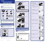
IMAGE FORMULA DR-6010C
Brand: Canon Pages: 2

DR-X10C - imageFORMULA - Document Scanner
Brand: Canon Pages: 2

DR-6080
Brand: Canon Pages: 22

DR-4580U
Brand: Canon Pages: 12
DR 5010C - imageFORMULA - Document Scanner
Brand: Canon Pages: 2

DR 2010C - imageFORMULA - Document Scanner
Brand: Canon Pages: 2

CR-50
Brand: Canon Pages: 14

CP Printer Solution Disk Version 4
Brand: Canon Pages: 16

CanoScan N676U
Brand: Canon Pages: 2

CANOSCAN N650U
Brand: Canon Pages: 6

CanoScan LiDE 35
Brand: Canon Pages: 14

DR 5010C - imageFORMULA - Document Scanner
Brand: Canon Pages: 96

700F - CanoScan LiDE
Brand: Canon Pages: 19

Duplex
Brand: Xerox Pages: 62

PRO-2049
Brand: Radio Shack Pages: 40

JOURNEE scan PA3712D-1ETC
Brand: Toshiba Pages: 2

GA-1330
Brand: Toshiba Pages: 31

GA-1330
Brand: Toshiba Pages: 38


