entegris Optimizer ST2, Инструкция по установке и эксплуатации
"entegris Optimizer ST2" - профессиональный прибор для оптимизации производственных процессов. Для правильной установки и использования необходимо скачать "Installation And Use Manual" совершенно бесплатно на manualshive.com. Этот руководство поможет максимально эффективно использовать функционал устройства.
Поделиться
Скачать


Отзывы:
Нет отзывов
Похожие инструкции для Optimizer ST2

6L
Бренд: NaturalSof Страницы: 12

Acro-Cal
Бренд: ViaAqua Страницы: 7

BIO-DYNAMIC LF 1000
Бренд: norweco Страницы: 6

Kaysun Aquantia R-32 PRO
Бренд: Frigicoll Страницы: 44

Scalekleen EV9796-01
Бренд: Everpure Страницы: 2

XP300-02
Бренд: Toro Страницы: 6

EVERPURE CONSERV LT-S
Бренд: Pentair Страницы: 20

ECOROCK-700
Бренд: Biorock Страницы: 47

GOLDLINE-50
Бренд: Good Water Warehouse Страницы: 10

WDF 10000 UV 11
Бренд: T.I.P. Страницы: 64

EWS 6
Бренд: A.O. Smith Страницы: 16

Brassmaster
Бренд: Water Control Страницы: 8
NL4-LBM Series
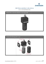
Бренд: Emerson Страницы: 3
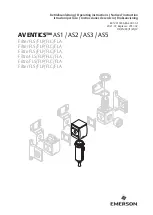
AVENTICS AS1
Бренд: Emerson Страницы: 47

LCO-8
Бренд: ROSEDALE Страницы: 6

FlowXtreme NE4487
Бренд: Bluewave Страницы: 20

Total Compact
Бренд: Aquaguard Страницы: 16

Reviva
Бренд: Aquaguard Страницы: 20


