EnGenius EAP150, Manual
The EnGenius EAP150 is a top-of-the-line wireless access point. With its sleek design and advanced features, it ensures seamless connectivity and enhanced network performance. For a hassle-free setup, the Quick Installation Manual can be downloaded for free from our website, enabling you to get started effortlessly.
Share
Download


Reviews:
No comments
Related manuals for EAP150
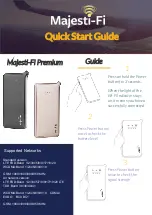
Premium
Brand: Majesti-Fi Pages: 2
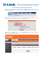
DSL-2750U
Brand: D-Link Pages: 3

AC866
Brand: IgniteNet Pages: 63

AP411W
Brand: Airlink101 Pages: 7

HH42CV2
Brand: TCL Pages: 23

RIVI RV65
Brand: HABITECH Pages: 3

Bridge/Router G-2000s
Brand: ZyXEL Communications Pages: 22

Rocket5AC R5AC-PTP
Brand: Ubiquiti Pages: 13

HHTSPT3GM42
Brand: Hamlet Pages: 10

cnRanger
Brand: Cambium Networks Pages: 61

Red CN-AP-2040
Brand: Cranberry Pages: 2

Orbi PRO SRS60
Brand: NETGEAR Pages: 2

LW140
Brand: SWEEX Pages: 8

LW310V2
Brand: SWEEX Pages: 32

Air Live Air4G
Brand: Ovislink Pages: 87

nr WRP64
Brand: Comet Labs Pages: 46

RLX-IH
Brand: RadioLinx Pages: 99

NXA-WAP1000
Brand: AMX Pages: 2


