Enfora GSM2374, User Manual
Get the most out of your Enfora GSM2374 with our comprehensive User Manual, available for free download at manualshive.com. This manual provides easy-to-follow instructions and valuable insights to optimize your experience with the product. Unlock the full potential of your Enfora GSM2374 with our user-friendly manual.
Share
Download


Reviews:
No comments
Related manuals for GSM2374

G31
Brand: YachtSafe Pages: 5

78-641
Brand: Blow Pages: 20

GV58LAU
Brand: Queclink Pages: 18
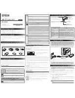
M-Tracer MT500G
Brand: Epson Pages: 2
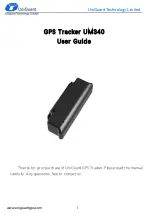
UM340
Brand: UniGuard Pages: 5

G626
Brand: Gosafe Pages: 26

957
Brand: NorthStar Pages: 70

EXPLORER 650
Brand: NorthStar Pages: 87

SMART-LINK GPS-T-SL
Brand: Ness Pages: 16
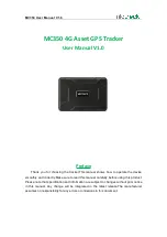
MC350
Brand: Mictrack Pages: 10

GPS Orion-S/-HD Receiver
Brand: Mitel Pages: 54

EV-07S
Brand: ASTA GPS TRACKERS Pages: 25

Hermes
Brand: Xeos Pages: 20
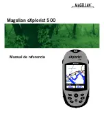
eXplorist 500 - Hiking GPS Receiver
Brand: Magellan Pages: 118

intelliroute TND 700
Brand: Rand McNally Pages: 2

Intelliroute TND-510
Brand: Rand McNally Pages: 2

84 series
Brand: Navigon Pages: 141

G600
Brand: Garmin Pages: 137


