

Emerson
®
Cybex
TM
SC KM 140/KM 145
4-Port KM Switches
Quick Installation Guide
1
To Contact Avocent Technical Support: Visit www.avocent.com
590-1230-501A
Emerson, Emerson Network Power and the Emerson Network Power logo are trademarks or service marks of Emerson Electric Co. Avocent, the Avocent logo and Cybex are trademarks or service marks of Avocent
Corporation. All other marks are the property of their respective owners. This document may contain confidential and/or proprietary information of Avocent Corporation, and its receipt or possession does not
convey any right to reproduce, disclose its contents, or to manufacture or sell anything that it may describe. Reproduction, disclosure, or use without specific authorization from Avocent Corporation is strictly
prohibited. ©2015 Avocent Corporation. All rights reserved.
HELPFUL RESOURCES
Product documentation downloads are
available at:
www.avocent.com/manuals
Search for additional product information at:
www.avocent.com
For further assistance, contact Avocent
Technical Support.
The following instructions will help you
install your Emerson
®
Cybex
TM
SC KM 140/
KM 145 switch.
WARNING
:
This product is equipped with
active intrusion protection. Tampering may
permanently disable the switch and void the
warranty. If the enclosure appears to have
been tampered with or if all the port LEDs
flash continuously, please contact Technical
Support. This product also has tamper evident
seals. Broken or removed seals will void the
warranty.
1
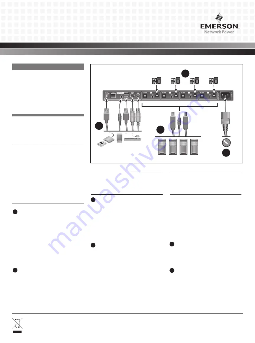
Connecting local peripherals
Turn off all computers you plan to use with
your SC KM 140/KM 145 switching system.
Plug the cable into the appropriate
CONSOLE port on the back of the switch.
Plug the USB or PS/2 keyboard and mouse
cables, audio (speaker/headset) cable and
Common Access Card (CAC) device into
the appropriate ports.
2
Connecting computers to the switch
Make sure all computers are turned off.
Plug the speaker, keyboard and mouse
cables from the corresponding computer
into one of the ports on the switch. Repeat
for all computers.
NOTE:
The cables must be connected directly
to an open USB port on your computer with no
USB hubs or other devices in between.
3
Turning on your system
Turn the monitor on. Plug the power
supply cord into the switch. Plug the other
end of the power supply cord into an AC
wall outlet.The display diagnostic LED
should be solid green a few seconds after
power is applied.
4
CAC device configuration and
operation
Using a USB cable, connect one end of the
cable to the computer that requires CAC,
and the other end to the CAC port on the
switch that corresponds to the computer.
Enable CAC for the port connection by
switching the CAC switch to the right.
Repeat the previous CAC steps for
additional computers that require CAC.
NOTE:
Make sure that the CAC switch is
disabled (switched left) for all other non-
connected CAC systems.
Once configured, the CAC connection will
be switched only when required by the
connected computer. When switching
from a CAC enabled port to a non-CAC
enabled port, the CAC connection will
remain with the last previously selected
port where CAC was enabled.
5
Turning on the computers
Turn on all the attached computers
and check for display and peripheral
functionality.
6
Switching your computers
When you turn on your computers, the
computer connected to the front panel will
be displayed. Press the corresponding front
panel button (1 through 4) on the switch to
access the computers on your SC switching
Emerson
®
Cybex
TM
SC KM 145 Switch Shown
1
4
3
2


