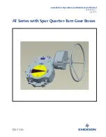
background image

Installation, Operation and Maintenance Manual


XXXXXX Rev. 1 

July 2016

AT Series with Spur Quarter-Turn Gear Boxes

Summary of Contents for AT Series

Page 1: ...Installation Operation and Maintenance Manual XXXXXX Rev 1 July 2016 AT Series with Spur Quarter Turn Gear Boxes ...

Page 2: ......

Page 3: ...n 3 1 Before Installation 5 Section 4 Installation 4 1 Mounting Types 6 Section 5 AT Series Gearbox Operation 5 1 Manual Use 7 5 2 Stopper Setting 8 Section 6 Lubrication 6 1 Application 10 Section 7 Disassembly and Reassembly Instructions 7 1 Removal of Cover 11 7 2 Disassembly of Spur Gear Reduction Unit 12 7 3 Dismantling of Worm Line Assembly 13 7 4 Removal of Worm Wheel 14 7 5 Reassembly of A...

Page 4: ...vice The torque is transmitted through the hand wheel and worm shaft which in turn drives the worm wheel thereby multiplying the torque transmitted from worm shaft to the valve stem which is connected to the worm wheel The purpose of this IOM manual is to help the user of this equipment on the following Safety instructions Installation of AT Series Gearboxes Operation of AT Series Gearboxes Mainte...

Page 5: ... has one valve mounting face on the bottom side either plain face or ribbed face depending on model and the worm wheel of the gearbox has a bore to suit the valve stem directly or suit the coupling between valve stem and gearbox This is so because the gearbox can be directly mounted onto the valve or it can be coupled with the valve with the help of a bracket and coupling Please find below differe...

Page 6: ...eries About the AT Series Figure 2 AT Series Exploded View 12 11 2 3 10 1 5 4 6 9 8 7 13 Table 1 Component List Component Number Part Name 1 Housing 2 Housing Cover 3 Gear 4 Worm 5 Bearing 6 Spur Housing 7 Spur Cover 8 Primary Pinion 9 Spur Gear 10 Stopper Bolt 11 O Ring 12 Indicator 13 Hand wheel ...

Page 7: ...Installation Operation and Maintenance Manual XXXXXXXX Rev 1 July 2016 4 Section 2 About the AT Series About the AT Series Figure 3 AT Series Bottom View PCD ID ...

Page 8: ...eriod less than 12 months it should be ensured that the gearbox is kept in a dry place preferably on a wooden pallet and protected from dust 4 If the AT Series gearbox is to be stored outdoors for a brief period less than 12 months it should be protected from coming in direct contact with rain with a canvas or something similar Also it should be kept on a wooden pallet or a raised platform to avoi...

Page 9: ...e valve might try to open the valve with a gearbox which is already in open position This will lead to excessive torque on the worm and worm wheel assembly which might lead to excessive wear breakage of internals 2 The gearbox should be positioned in such a way so that clockwise rotation of hand wheel gives clockwise rotation of output to close the valve 3 Check whether the mounting dimensions ste...

Page 10: ... with a hand wheel which is supplied along with the gearbox 2 Do not manually operate the gearbox with devices other than the hand wheel Using cheater bars wheel wrenches or other such devices on the gearbox hand wheel may cause serious injury and or damage to the gearbox or valve 3 In standard applications clockwise rotation of hand wheel gives clockwise rotation of output to close the valve Figu...

Page 11: ...scribed below 3 Withdraw the stoppers completely Rotate the valve to the fully closed position by rotating the hand wheel clockwise Once the valve is fully closed advance the stopper till it touches the sector gear Secure this stopper position with a nut 4 Similarly for stopper setting at fully open position of the valve withdraw the stopper at open side completely Rotate the valve to the fully op...

Page 12: ...Installation Operation and Maintenance Manual XXXXXXXX Rev 1 July 2016 9 Section 5 AT Series Gearbox Operation AT Series Gearbox Operation Figure 6 Stopper Bolt Location Stopper Bolt ...

Page 13: ...ries gearboxes are supplied with EP 1 premium quality lithium soap based grease NLGI grade 1 suitable for an ambient temperature of 20 to 120 in case of specialty greases the temperature range could be different 3 Grease should be changed after 6 months if the gearbox is in continuous operation whereas it should be changed after 12 months if it is operated intermittently 4 Do not mix different gre...

Page 14: ... 7 Disassembly and Reassembly Instructions 7 1 Removal of Cover Remove the cover by loosening the cover bolts with a spanner Each time the cover is removed the gasket sealing is lost as it is a liquid sealant Re apply gasket sealant Loctite no 596 or equivalent Take proper care not to damage the mating surface of the cover Figure 7 Cover Removal ...

Page 15: ...with a spanner Each time the cover is removed the gasket sealing is lost as it is a liquid sealant Re apply gasket sealant Loctite no 596 or equivalent Figure 8 Spur Gear Bolts Both spur pinions and spur gears can be removed with a circlip plier once the cover is removed Remove the spur gear unit casing by loosening the allen cap screws with which it is mounted on the main AT Series GB casing Figu...

Page 16: ...ly Loosen the grub screw and key spring pin with which the worm is fixed to the input shaft Pull the input shaft out of the main housing This will disassemble the entire worm line assembly Now remove the worm and all other small parts like spacers washers bearings etc from this assembly Figure 10 Grub Screw Removal Grub Screw Key Figure 11 Removal of Spring Pin Spring Pin ...

Page 17: ... lifting it from the gearbox housing Replace and lubricate the O rings in the housing before reassembling the worm wheel Figure 12 Removing the Worm Wheel 7 5 Reassembly of AT Series Gearbox In reassembly of the AT Series gearbox follow all above steps in reverse order Be sure to lubricate all mating rotating parts with grease Ensure to provide a liquid sealant on both covers and housing ...

Page 18: ...XXXXXX Rev 1 July 2016 15 Section 8 Document Revision Document Revision Section 8 Document Revision Table 2 Revision Overview ECN DATE REVISION STATUS BY DATE XXXXXX 6 16 2016 1 Completed Charles Rico 6 16 2016 Signatures on file Bettis Houston Texas ...

Page 19: ...T Series Exploded View 3 Figure 3 AT Series Bottom View 4 Figure 4 Hand Wheel Rotation 7 Figure 5 Another View of Hand Wheel Rotation 8 Figure 6 Stopper Bolt Location 9 Figure 7 Cover Removal 11 Figure 8 Spur Gear Bolts 12 Figure 9 Spur Housing Disassembled 12 Figure 10 Grub Screw Removal 13 Figure 11 Removal of Spring Pin 13 Figure 12 Removing the Worm Wheel 14 ...

Page 20: ......

Page 21: ...ongmeadow Business Estate East P O Box 6908 Greenstone 1616 Modderfontein Extension 5 South Africa T 27 11 451 3700 EUROPE Holland Fasor 6 Székesfehérvár 8000 Hungary T 36 22 53 09 50 Strada Biffi 165 29017 Fiorenzuola d Arda PC Italy T 39 0523 944 411 www emerson com bettis 2018 Emerson All rights reserved The Emerson logo is a trademark and service mark of Emerson Electric Co BettisTM is a mark ...

Reviews: