


Primary Glass Panel Engine Monitor
Primary Glass Panel Engine Monitor
Primary Glass Panel Engine Monitor
Primary Glass Panel Engine Monitor
Primary Glass Panel Engine Monitor
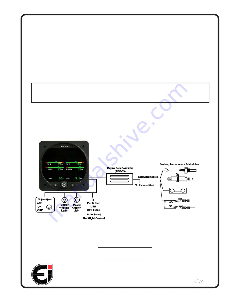
CGR-30C
CGR-30C
CGR-30C
CGR-30C
CGR-30C
Installation Instructions
Installation Instructions
Installation Instructions
Installation Instructions
Installation Instructions
II 10291301
Electronics International Inc.
Electronics International Inc.
Electronics International Inc.
Electronics International Inc.
Electronics International Inc.
®
®
®
®
®
Rev: B, 5/11/15*
63296 Powell Butte Hwy • Bend, OR 97701 • (541) 318-6060 • Buy-EI.com
63296 Powell Butte Hwy • Bend, OR 97701 • (541) 318-6060 • Buy-EI.com
63296 Powell Butte Hwy • Bend, OR 97701 • (541) 318-6060 • Buy-EI.com
63296 Powell Butte Hwy • Bend, OR 97701 • (541) 318-6060 • Buy-EI.com
63296 Powell Butte Hwy • Bend, OR 97701 • (541) 318-6060 • Buy-EI.com
Model #:
Model #:
Model #:
Model #:
Model #:
S/N:
S/N:
S/N:
S/N:
S/N:
You must read this manual before installing or operating the instrument. This
manual contains warranty and other information that may affect your decision
to install this product and/or the safety of your aircraft.
The CGR-30C is a FAA Approved Primary Replacement
for Engine and Aircraft System Instruments


