Electronics Diversified Plus, User Manual
Introducing Hoover Plus - The ultimate user manual for your Hoover appliances! Download our comprehensive manual, absolutely free, from manualshive.com today. Our easy-to-use guide provides step-by-step instructions and valuable tips to maximize the potential of your Hoover products. Get your hands on the essential manual now!
Share
Download


Reviews:
No comments
Related manuals for Plus
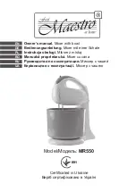
MR550
Brand: Maestro Pages: 52

GM Series
Brand: Faggiolati Pumps Pages: 38

Cloud key Gen2 Plus
Brand: UniFi Pages: 46

Tri-ger
Brand: Qu-Bit Electronix Pages: 13

PPDLC1
Brand: Pyle Pages: 1

DANALOG DDX3216
Brand: Behringer Pages: 22

MM-14FX
Brand: Nady Audio Pages: 2

RUBIMIX-7
Brand: Rubi Pages: 52

1202-VLZ MicroSeries
Brand: Mackie Pages: 10

BigRock Pro
Brand: Amptweaker Pages: 4

HM 638
Brand: Hyundai Pages: 32

HM628
Brand: Hyundai Pages: 32

Mix-360
Brand: Steren Pages: 26

MGSTSL5010-449
Brand: Oster Pages: 12

2384
Brand: Oster Pages: 40

7 Speed Clean Start Hand Mixer
Brand: Oster Pages: 2
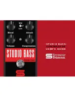
STUDIO BASS
Brand: Duncan Pages: 12

Killing Floor
Brand: Duncan Pages: 12


