background image

Publication #5995523544                                                                                 Revision B       August  2010                       

Technical Service Manual

Wave-Touch™ & IQ-Touch™

Front-Load Washer

Models

EWFLW65H & EIFLW55H

Summary of Contents for EIFLW55H MB

Page 1: ...Publication 5995523544 Revision B August 2010 Technical Service Manual Wave Touch IQ Touch Front Load Washer Models EWFLW65H EIFLW55H ...

Page 2: ......

Page 3: ... standard color coding for safety ground wires is GREEN or GREEN with YELLOW STRIPES Ground leads are not to be used as current carrying conductors It is EXTREMELY important that the service technician reestablish all safety grounds prior to completion of service Failure to do so will create a hazard 7 Prior to returning the product to service ensure that All electrical connections are correct and...

Page 4: ...13 Reattaching Hinge to Front Panel 2 13 Removing Striker Plate 2 14 Removing Latch Indicator 2 14 Removing Hole Plug 2 15 Reinserting Latch Indicator 2 15 Reattaching Striker Plate 2 16 Reinserting Hole Plug 2 16 Reattaching Door Assembly 2 16 Reversing Trim Ring 2 17 Reinstalling Trim Ring 2 17 Reinstalling Trim Plug 2 17 Accessories 2 18 Matching Storage Pedestal 2 18 Dryer Stacking Kit 2 18 Dr...

Page 5: ... 14 Power Cord 4 15 Rear Access Cover 4 15 Suspension Spring 4 15 Top Center Brace 4 16 Electric Water Level Sensor 4 16 Drain Pump 4 16 Drive Belt 4 17 Large Pulley 4 17 Drive Motor 4 17 Speed Control Board Assembly 4 18 Air Bell 4 18 Heating Element 4 19 Air Shock Absorber 4 19 Tub Assembly 4 20 Section 5 Troubleshooting 5 1 Troubleshooting Chart 5 1 Component Resistance Chart 5 5 Section 6 Wiri...

Page 6: ...er turn on all hot water faucets and let the water flow from each for several minutes This will release any accumulated hydrogen gas Hydrogen gas is flammable do not smoke or use an open flame during this time Do not store or use gasoline or other flammable vapors or liquids in the vicinity of this or any other appliance Failure to comply with these warnings could result in fire explosion serious ...

Page 7: ...ccidental operation by children 5 Temperature Selections 5 Spin Speed Selections 3 Soil Level Selections ATC Automatic Temperature Control Product Specifications Wave Touch Washer 2 Premium Colors Enhanced LCD Controls with larger trilingual display 1350 RPM Quiet 52 72 dBA Multiple User Mode 3 User Modes with Favorite and Custom Cycles 11 Standard 3 Favorite Cycles with custom settings to reach 4...

Page 8: ...er used for a given fill and temperature selection The following are the temperature ranges for the wash rinse cycles Temperature Setting Temperature Range Sanitize 67 C 152 F 5 C Hot 55 C 131 F 5 C Eco Hot 45 C 113 F 5 C Warm 29 C 84 F 4 C Eco Warm 27 C 81 F 3 C Warm Rinse 24 C 75 F 3 C Cold 15 C 59 F 5 C Water Level The spinner tub vanes must not be in water during this check Check is taken at t...

Page 9: ...re is a child entrapment safety feature that allows a child to push from the inside of the unit with less than 15 pounds of force and the door will open but only when the door is unlocked When in the unlatched position there is one electrical and two mechanical features that prevent the door lock from being able to lock Electronic Water Level Switch The electronic water level sensor is mounted to ...

Page 10: ...ar corner of the washer The speed control board controls the following operations 1 The speed of the drive motor is controlled by converting input line to neutral single phase 60 Hertz voltage to a varying frequency three phase output voltage from zero to 300 VAC By varying the amount frequency and polarity of the voltage and comparing the input from the tachogenerator on the drive motor the speed...

Page 11: ...s water from the left hand input as viewed from the front of the washer The pre wash channel forms a loop that allows the water to pass over the pre wash detergent section of the drawer As the water passes over the pre wash detergent section holes in the cavity allows some of the water to enter and flush the pre wash detergent cavity Since the flow of the incoming water is more than the holes can ...

Page 12: ...l forms a loop that allows the water to pass over the fabric softener cavity section of the drawer As the water passes over the fabric softener section holes in the cavity allow some of the water to enter and mix with the fabric softener This raises the mixture level above the tubes in the drawer fabric softener cavity allowing the mixture to flow into the tub Like the detergent channel the flow o...

Page 13: ...in pump off The drain pump will then turn on for one minute and attempt to drain the tub of water and or suds If pressure can not be brought to zero and this happens twice in a given intermediate rinse cycle then the spin cycle is skipped and if it is the second intermediate spin first for the Fast Cycle then up to 3 rinse cycles will be added to eliminate suds in the tub The Language of Laundry M...

Page 14: ...1 12 Basic Information Notes ...

Page 15: ... RECOMMENDED DO NOT INSTALL OR USE A DAMAGED APPLIANCE IF YOU RECEIVE A DAMAGED APPLIANCE IMMEDIATELY CONTACT YOUR DEALER OR BUILDER DO NOT USE THE WASHER UNTIL IT HAS BEEN PROPERLY INSTALLED BY A QUALIFIED INSTALLER ACCORDING TO THESE INSTALLATION INSTRUCTIONS THE INSTALLER MUST SHOW THE CUSTOMER THE LOCATION OF THE POWER PLUG SO THAT THEY KNOW WHERE AND HOW TO DISCONNECT POWER TO THE WASHER DO N...

Page 16: ... PREVENT PERSONAL INJURY OBSERVE ALL WARNINGS ON PRODUCT LABELS CUT HAZARD TO PREVENT SERIOUS INJURY FROM SHARP EDGES WEAR WORK GLOVES WHEN HANDLING UNPACKING OR DISASSEMBLING UNIT EXCESSIVE WEIGHT HAZARD To avoid back or other injury have more than one person move or lift the dryer The electrical service to the dryer must conform with local codes and ordinances and the latest edition of the Natio...

Page 17: ... and ordinances or in the absence of local codes with the National Electrical Codes ANSI NFPA 70 latest edition If in doubt call a licensed electrician DO NOT cut off or alter the grounding prong on the power supply cord In situations where a two slot receptacle is present it is the owner s responsibility to have a licensed electrician replace it with a properly grounded three prong grounding type...

Page 18: ...m Maximum height 96 in 244 cm Removing Foam Packaging 1 Temporarily remove door tape 2 Open washer door and remove everything from the drum 3 Close door and reapply door tape 4 Using a rug blanket or piece of cardboard to protect the floor carefully lay washer on it s back 5 Remove styrofoam base and shipping plug and set them aside 6 Carefully return washer to an upright position 7 Carefully move...

Page 19: ...en a door is installed A louvered door with equivalent air openings for the full length of door is acceptable Figure 2 4 Closet Installation Figure 2 5 Clearances DO NOT INSTALL THE WASHER 1 In an area exposed to dripping water or outside weather conditions The ambient temperature should never be below 60 F 15 6 C to maximize detergent effectiveness 2 In an area garage or garage type building wher...

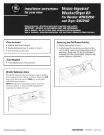
Page 20: ...Installation Information 2 6 Installed Washer Dimensions ...

Page 21: ... material on spacers may need time to relax before they can be easily pulled through shipping hole Save all shipping bolts and spacers for future use If the washer is to be transported at a later date the shipping hardware must be reinstalled to help prevent shipping damage ...

Page 22: ...et Water 1 Run some water from the hot and cold faucets to flush the water lines and remove particles that might clog the water valve screens and to determine which faucet is hot and which is cold supply 2 Look in the end of each water supply inlet hose and verify that the rubber washers are in place 3 Connect the HOT inlet hose to the HOT water supply and the COLD inlet hose to the COLD water sup...

Page 23: ...ed in the enclosure package to the standpipe inlet hose laundry tub etc so the hose does not pull out from the force of the water 3 Plug the power cord into a grounded outlet 4 Turn on the power at a circuit breaker fuse box 5 Carefully slide the washer to its final position Recheck for level and rock corners for stability Remove and discard door tape Figure 2 7b Drain Hose Installation A wiring d...

Page 24: ...ly and simultaneously press and hold both the eco friendly and my favorite buttons for 5 seconds or until the LCD display changes 4 The LCD window will display INSTAL CYCLE and show estimated time of cycle completion Press the START button The Installation Cycle will automatically test for if the water has been turned on At cycle completion the LCD window may display INSTAL PASS meaning the washer...

Page 25: ...ree angle 2 Remove and save the trim plug and long course thread panhead screw See Figure 2 8 3 Close the door 4 Rotate the door trim approximately counter clockwise and pull it away from the front of the door See Figure 2 9 Removing Door from Hinge 1 Reopen door to 90 degree angle 2 Remove 4 long course thread counter sunk hinge screws from door See Figure 2 10 3 While supporting the weight of th...

Page 26: ...elease harness from the retainer allowing the harness to lay outside the front panel See Figure 2 14 Removing Door Lock from Front Panel 1 Remove 2 short course thread panhead screws from the door lock See Figure 2 15 2 Slide the lock toward the outer edge of the front panel Pivot the lock slightly outward while slowly pulling it through opening to expose the attached harness See Figure 2 16 3 Rel...

Page 27: ...igure 2 20 Reattaching Hinge to Front Panel 1 Rotate the hinge and move it to the opposite opening 2 Connect the harness to the hinge retainer by inserting it in the retention terminal and gently pushing until you hear the fastening tab click See Figure 2 21 3 Gently pull on the harness to be sure it is secure 4 Use the side locating pins to align the hinge and install 1 short fine thread counter ...

Page 28: ...moving Latch Indicator 1 Grasp the indicator on the latch side between finger and thumb and rock it upward pivoting away from the center of the glass See Figure 2 25 2 Gently push the indicator toward the center of the lens to release the tab 3 Rock the tab upward See Figure 2 26 4 Pull the indicator out and set it aside See Figure 2 27 Figure 2 24 Figure 2 25 Figure 2 26 Figure 2 27 ...

Page 29: ... the lock toward the center of the front panel until the screw holes line up See Figure 2 29 4 Secure the lock with 2 short course thread panhead screws Reinserting Latch Indicator 1 Rotate the latch indicator and move it to the opposite hole in the door 2 Grasp the indicator between finger and thumb and slide it through the opening See Figure 2 30 3 Gently push the indicator toward the center of ...

Page 30: ...g Striker Plate 1 Rotate the striker plate and move it to the opposite side of door above the indicator 2 Reattach with 2 long course thread counter sunk screws See Figure 2 32 Reinserting Hole Plug 1 Rotate the hole plug and move it to the opposite hole in the door 2 Grasp the hole plug between finger and thumb and insert the tab into the retaining slot See Figure 2 33 3 Pivot the hole plug downw...

Page 31: ...lling Trim Ring 1 Close the door 2 Orient the trim so 12 position is approximately to the left of top center The opening in the trim ring should be on the hinge side 3 Insert the trim ring in the slots and rotate it clockwise approximately See Figure 2 37 UP Reinstalling Trim Plug 1 Open the door to a 90 degree angle 2 Install the trim plug with 1 long course thread panhead screw See Figure 2 38 3...

Page 32: ...destal will add about 15 38 1cm to the height of your unit for a total height of 53 134 62 cm Dryer Stacking Kit A kit for stacking the matching dryer on top of this washer is available with the purchase of the matching dryer Drain Hose Extension Kit In order to reach standpipe heights or distances beyond the reach of the drain hose supplied order the DRAIN HOSE EXTENSION KIT Universal Appliance W...

Page 33: ...llation instructions packed with each appliance prior to stacking 4 Be sure washer and dryer are both unplugged Preparing Dryer for Stacking 1 If already installed disconnect dryer from electrical and gas connections and exhaust venting On models with Steam Option disconnect water supply to dryer 2 Protect floor with cardboard or other covering and carefully tip dryer onto its back See Figure 2 41...

Page 34: ...her 2 Hold the front of the dryer up slightly carefully slide the dryer back 3 Slide hook tabs on rear brackets into slots in back sheet of dryer Dryer will be approximately left of center Continue sliding dryer back until tabs are fully engaged See Figure 2 46 4 Slide dryer approximately to the right centering it on washer and hooking rear bracket tabs into slots on back 5 Lift front of dryer and...

Page 35: ... left to disengage dryer from rear brackets 5 Support the front of the dryer clearing the front bracket while sliding the dryer forward Have two or more people lift the dryer off the washer and gently place it on the floor Figure 2 48 If laundry appliances must be moved front and rear mounting brackets may remain attached to the washer top until the dryer is restacked To permanently unstack the un...

Page 36: ...Installation Information 2 22 Notes ...

Page 37: ...in set prefs under the options scroll buttons Demo Mode Demo Mode will standby for 10 minutes then perform an LED on off sequence for 3 minutes During the standby sequence the drum light and start button will be activated The controls will be fully functional during Demo Mode with abbreviated cycles lasting about 1 minute Some features will be deactivated during Demo Mode for safety purposes When ...

Page 38: ...Electronic Control 3 2 Wave Touch Washer Cycle Chart ...

Page 39: ... seconds Demo Mode Demo Mode will standby for 10 minutes then perform an LED on off sequence for 3 minutes During the standby sequence the drum light and start button will be activated The controls will be fully functional during Demo Mode with abbreviated cycles lasting about 1 minute Some features will be deactivated during Demo Mode for safety purposes When the units are in Demo Mode the text D...

Page 40: ...Electronic Control 3 4 IQ Touch Washer Cycle Chart ...

Page 41: ...vels and options except warm rinse are available with this cycle Whites The whites cycle provides 9 21 minutes of reversing tumble wash action for whiter cottons The use of liquid chlorine bleach is recommended Hot temp and eco hot temp water all spin speeds and soil levels and all options except warm rinse are available with this cycle Heavy Duty The heavy duty cycle provides 9 21 minutes of reve...

Page 42: ... 66 C an automatic cool down and drain will occur before the door can be opened Casual The casual cycle provides 5 20 minutes of revers ing tumble action for cottons and blends with a permanent press or no iron finish All temperatures except sanitize temp all spin speeds and soil levels and all options except warm rinse are available with this cycle Active Wear The active wear cycle provides 5 17 ...

Page 43: ...tting Select the speed appropriate for the load for 8 minutes of spin To add a cold water rinse prior to the spin select the extra rinse option My Favorite IQ Touch To program a cycle with a preferred water temperature spin speed soil level and options press and hold the MY FAVORITE button for 3 seconds To use that customized cycle to wash future loads simply press the MY FAVORITE button and the s...

Page 44: ... under change users 3 Select another user s name 4 Press the button under EXIT 5 The icon for the last cycle run will light up 6 Turn the cycle selector knob to my favorites 7 Select one of the 3 customized cycles by pressing the corresponding button 8 Press the start button To select a user if a user s name is not displayed when the washer is turned on 1 Press the options buttons to scroll to set...

Page 45: ...perature in some geographic areas can affect water temperature Cold Temp Use this setting for lightly soiled brightly colored items knits delicates hand washables and washable silk Eco Warm Temp Reduces the warm water temperature a few degrees to save energy when washing normally soiled colorfast cottons sheets casual items and washable woolens Warm Temp Use this setting for normally soiled colorf...

Page 46: ...l of each load Normal soil heavy soil extra heavy soil heaviest soil light soil and extra light soil levels are available IQ Touch Washing Rinsing Temperature Sanitize Cold This setting sanitizes heavily soiled colorfast fabrics such as towels bedding and children s clothing by killing 99 9 of bacteria using wash water heated with a boost heater to 152 F 67 C Cold water is used to cool and rinse t...

Page 47: ... except deep clean sanitize and spin only Stain Clean Use the stain clean option to add a 5 minute soak in the middle of the wash portion of the normal colors casual active wear whites heavy duty and deli cates cycles Extra Rinse Use this option when additional rinsing is desired to remove excess dirt or detergent It is recom mended for heavily soiled loads or if household members have sensitive s...

Page 48: ... will prewash in cold water for 5 minutes The water will drain and the load will automatically advance to the selected wash cycle Warm Rinse Select the warm rinse option with the normal heavy duty active wear fast wash delicates and hand wash cycles Delay Start Use delay start to select a wash time convenient to your schedule or during off peak energy hours The start of any cycle can be delayed fo...

Page 49: ...E OPTIONS GUIDE and SET PREFS GUIDE for descriptions of the cycles water temperatures spin speeds soil levels cycle options and features for user preferences Stain Guides Scroll through the stain guide to the desired stain category Press the select button for safe successful stain removal instructions Control Lock To lock the controls between cycles scroll to the control lock feature press select ...

Page 50: ...down button until you reach save as favorite 6 Press the select button to enter the favorite cycle choice screen 7 Press the button under my favorite 1 To name the customized cycle for shirts press MY FAVORITE 1 Press the button under ABC to name the favorite cycle alphabetically Use the button under 1A to add numbers foreign language characters or symbols to the name Rotate the cycle selector kno...

Page 51: ... character to let the cursor advance Press the button under DELETE to erase incorrect entries There is a blank character between Z and A for inserting spaces in your custom name Pause momentarily on this character as you would to insert any other character then continue When the name has been entered press select to save the name To edit names while in CUSTOM MODE turn the washer off by pressing c...

Page 52: ... or restore all factory defaults both cycle settings and factory preferences Press the button under EXIT to return to normal operation or press the cancel button to turn the washer off without making any changes If you do not make a selection within 30 seconds the washer will return to normal operation without any changes If you reset all settings INSTALL CYCLE will be displayed as though the wash...

Page 53: ...for each cycle To delete the display press select To restore the display press select and CYCLE DESC ON press SELECT to turn OFF will appear in the LCD User Interface Status Display The estimated total cycle time will be displayed when the cycle is selected The time may increase if water pressure is low oversudsing occurs or the load becomes unbalanced The approximate time remaining will be displa...

Page 54: ... to begin the cycle Installation cycle will test for electronic issues wiring issues water flow issues At cycle completion the display will show INSTAL PASS or prompt an action during the cycle such as CALL SERVICE NO WATER or CHECK HOSES Correct the action and repeat the cycle for proper installation Washer will exit the Install Cycle and return to normal operation the next time the knob is turne...

Page 55: ...ode Press the CANCEL button to enter standby mode and enable diagnostic entry 1 Within 10 seconds after pressing CANCEL press any button to wake up the control 2 Within 5 seconds of wake up turn the selector knob to the far left cycle and press and hold the CANCEL and the far left button under the display simultaneously for 3 seconds to enter the Diagnostic Mode NOTE To save time at wake up the we...

Page 56: ...he softener compartment 5 Turn the program knob 4 clicks from the start position The prewash solenoid will activate and cold water should enter through the prewash compartment 6 Turn the program knob 5 clicks from the start position The door lock solenoid will deactivate and the loading door can be opened When the door is opened the drum light should turn on 7 Turn the program knob 6 clicks from t...

Page 57: ...Electronic Control 3 21 Error Code Chart ...

Page 58: ...Electronic Control 3 22 Error Code Test Chart ...

Page 59: ...Electronic Control 3 23 Error Code Test Chart ...

Page 60: ...Electronic Control 3 24 Notes ...

Page 61: ...ATION SHOULD ONLY BE PERFORMED BY A TRAINED AUTHORIZED SERVICE TECHNICIAN OR INSTALLER TO AVOID ELECTRIC SHOCK POWER TO A WASHER UNIT MUST BE DISCONNECTED WHENEVER ACCESSING AND OR REMOVING COMPONENTS POWERED BY ELECTRICITY OR COMPONENTS NEAR OTHER ELECTRICAL COMPONENTS AFTER SERVICE IS COMPLETED BE SURE ALL SAFETY GROUNDING CIRCUITS ARE COMPLETE ALL ELECTRICAL CONNECTIONS ARE SECURE AND ALL ACCES...

Page 62: ... Figure 4 1 3 Close the door 4 Rotate the door trim approximately counter clockwise and pull it away from the front of the door See Figure 4 2 Door Assembly Removal The door assembly is secured with 4 screws to the hinge assembly It is not necessary to remove the trim ring to access the hinge screws of the door assembly To remove the door assembly 1 Open the door to a 90 degree angle 2 Using a 2 s...

Page 63: ...hat are mounted to the inner door assembly To remove the inner door glass 1 Remove door assembly from unit 2 Remove the striker plate 3 Using a 2 square bit screwdriver extract the screws from the two retaining covers and pull from door assembly See Figure 4 6 4 Lift the inner door glass from door assembly Latch Indicator Removal The latch indicator is secured by retaining latches to the interior ...

Page 64: ...r hinge 1 Remove door assembly from unit 2 Using a 2 square bit screwdriver with the hinge in open position extract two short course thread panhead screws on hinge plate See Figure 4 10 3 Using a 2 square bit screwdriver extract 3 short fine thread countersunk screws in hinge side See Figure 4 11 4 Slide the hinge toward the center of the front panel and then pivot the hinge inward while slowly pu...

Page 65: ... and a mounting cavity for the interior light and the Advanced Rinse Technology ART hose A spring loop retains the bellows to the front panel of the washer and to the inner wash tub The bellows must be released from the front panel before removing the front panel to access the spring loop on the wash tub To remove the bellows 1 Remove the door 2 Pull back the top section of the bellows at the top ...

Page 66: ... the bellows into the lip of the tub 4 Using your thumb start on the other side of the top tab and force the bellows on in the other direction Again about one third of the way around stop and seat the bellows onto the tub lip Force the remaining bellows on with your thumb and seat it See Figure 4 18 5 To install the spring fold the front of the bellows back into the tub 6 Place the spring in the g...

Page 67: ...t corner and two screws at the rear of the unit To remove the top panel 1 Pull unit from its installation position to access the rear of the unit 2 Using a 2 square bit screwdriver extract the two screws securing the top panel to the unit frame See Figure 4 21 3 From the front of the unit push the top panel towards the rear until free of the metal tabs then lift top panel off of unit Vibration Dam...

Page 68: ... a mounting surface for the user interface and LCD screen Screws secure the console panel to the unit frame The wire harness connects to the control assembly at the far right hand side behind the console panel To remove the console panel 1 Remove the detergent drawer and top panel 2 Using a 2 square bit screwdriver extract the three screws from the detergent drawer area See Figure 4 24 3 From the ...

Page 69: ...ith the Start Pause button Lift slightly and pull tab out of the slot closest to the cycle selector knob 4 Separate the cycle control knob housing from the control assembly by releasing the three retaining latches on the outer edge of the control assembly Carefully lift up housing until control knob is free of shaft then lift housing off of the control assembly NOTE When removing the control board...

Page 70: ... frame along the top right front edge The wire harness connects to the controller board with three Molex connectors through the controller box and four Molex connectors under the controller box lid To remove the controller assembly 1 Remove the top panel and control console 2 Disconnect the Molex connector leading to the wire harness of the door latch at the upper right hand corner next to the con...

Page 71: ...e 4 29 7 Carefully slide weight ring off of wash tub Water Inlet Overflow Vent Tube Grommet The water inlet overflow vent tube grommet supports the hot and cold water inlet fittings and the overflow tube The overflow tube must be removed prior to removing the grommet To remove the water inlet overflow vent tube grommet 1 Disconnect the washer from the hot and cold water hoses See Figure 4 30 2 Usi...

Page 72: ...bly is mounted with three screws to the back of the detergent dispenser The inlets are color coded as well as the valves and connectors for the wire harness To remove the water inlet valve assembly 1 Disconnect the washer from the hot and cold water hoses 2 Remove the top panel water valve and over flow vent tube grommet and the overflow vent tube 3 Disconnect the wiring harness from the valves an...

Page 73: ...mp outlet runs to a split grommet in the rear upper left hand corner where it passes through the rear panel en route to the house drain Retaining straps secure the drain hose to the base and sidewall of the unit To remove the external drain hose 1 Remove the front and top panel 2 Using a pliers compress the hose clamp from the outlet hose of the drain pump and disconnect See Figure 4 36 3 From the...

Page 74: ... each side locking the housing to the console mounting panel See Figure 4 39 8 Slide the housing back until the tab of the top center brace release and the housing drops down See Figure 4 39 9 Using a pliers disconnect the advanced rinsing technology hose See Figure 4 40 10 Push down on the tub and swing the front of the housing toward the center of the washer Work the housing out from under the c...

Page 75: ...n position 2 Using a 2 square bit screwdriver extract the six screws securing rear access cover to the rear panel See Figure 4 43 Suspension Spring Removal The suspension springs are located under a cover bracket mounted on the top center brace To remove the suspension springs 1 Remove the top panel 2 Remove the overflow vent tube 3 Using a 2 square bit screwdriver extract the two screws from each...

Page 76: ...uarter turn to release it from the side panel and pull out on the pressure switch 4 Using a pliers compress the hose clamp and remove hose from sensor Drain Pump Removal The drain pump is mounted to the front base of the unit and is secured with a retaining tab and screw To remove the drain pump 1 Remove control console and front panel 2 Disconnect the wire harness from the left side of the drain ...

Page 77: ...clockwise See Figure 4 49 Drive Motor Removal The drive motor is secured with four bolts to the bottom of the wash tub assembly The ground wire connects to a terminal to the front of the drive motor that can be accessed from the rear access panel To remove the drive motor 1 Remove rear access panel 2 Remove the drive belt 3 Disconnect the electrical plug and the ground wire from the drive motor Se...

Page 78: ...rive control assembly towards rear access panel hole to access the wire harness connections Cut wire retainers securing the wire harness to the drive control assembly 7 Release the retaining latches securing the cover to the speed control assembly 8 Disconnect all wire harness connections from the speed control assembly See Figure 4 53 Air Bell Removal The air bell is mounted on the right side of ...

Page 79: ...nt 1 Remove the rear access panel 2 Disconnect the wires from the heating element drum water NTC Negative Thermal Coefficient and ground wire See Figure 4 55 3 Using a 10mm extended socket loosen the compression nut and pull the heater assembly out of the drum Air Shock Absorber Removal Four shock absorbers one mounted to each corner of the wash tub assembly stabilize the wash tub during operation...

Page 80: ...om the tub 5 If replacing the front half of the outer tub remove the bellows and the weight ring 6 Remove the small hose from the air bell 7 Remove the large pulley drive motor and speed control board assembly 8 Remove the top pins from shock absorbers and push the shock absorbers against the cabinet 9 Place protective material on floor then carefully turn the washer on its face and release the su...

Page 81: ... on its side reinstall the screw that holds the large pulley on and tap the inner tub out with a rubber hammer See Figure 4 61 NOTE The bearings water seal and seal between the two tubs come as part of the rear half of the outer tub If the water seal or bearings fail inspect and if necessary dress the shaft of the spin basket with a file With some failures it may be necessary to replace the spin b...

Page 82: ...Component Teardown 4 22 Notes ...

Page 83: ...ller 1 Use a lint brush or shaver to remove pills 2 Use fabric softener in the washer to lubricate fibers 3 When ironing use spray starch or fabric finish on collars cuffs 4 Turn items inside out to reduce abrasion Problem Correction 1 Undiluted liquid detergent or fabric softener dispensed directly onto fabric 1 Not enough detergent 2 Wash temperature too low 3 Incorrect sorting 1 Not enough dete...

Page 84: ...rmanent press cycle Increase detergent Add bleach or treat with color remover 1 To restore discolored load of whites use rust remover safe for fabric 2 Do not use chlorine bleach to remove rust stains It may intensify discoloration 3 Use nonprecipitating water softener 4 Before washing run hot water for a few minutes to clear lines 5 Drain water heater occasionally 6 For an ongoing problem install...

Page 85: ... turned off 5 Close dispenser drawer 1 Close door completely 2 Close dispenser drawer 3 Add 1 or 2 similar items to help balance the load Problem Correction 1 A certain amount of motor whine is normal during the spin cycle 1 Foreign objects such as coins or safety pins maybe in drum or pump 2 Belt buckles and metal fasteners are hitting wash drum 1 Washer is overloaded 1 Heavy wash loads may produ...

Page 86: ...just water heater as necessary 2 Avoid using hot water elsewhere before or during washer use There may not be enough hot water available for proper cleaning If problem persists the hot water system may be unable to support more than 1 use at a time 1 Clean and straighten the drain hose 2 Maximum standpipe height is 8 2 4 m 1 Check and tighten hose connections Install rubber sealing washers provide...

Page 87: ...ycle 3a Press and hold CANCEL button and CTRL LOCK button for 3 seconds IQ Touch 3b Press and hold CANCEL button and SOIL LEVEL Third button from the left for 3 seconds Wave Touch Problem Correction 1 Hot and cold water hoses are connected to wrong supply faucets 1 Drain hose standpipe is incorrect height 1 Washer has been programmed to temporarily perform a repeating demo cycle Cause Electrical C...

Page 88: ...Troubleshooting 5 6 Notes ...

Page 89: ...Wiring Schematics 6 1 Model EWFLW65H EIFLW55H ...

Page 90: ...Wiring Schematics 6 2 Notes ...

Reviews: