ELECTRO FREEZE COMPACT Series, Operator'S Manual
The ELECTRO FREEZE COMPACT Series is an innovative and efficient machine designed to bring your frozen treat business to new heights. Stay ahead of the game with our easy-to-use Operator's Manual, available for free download from our website. Master the art of frozen treat making with our comprehensive manual, ensuring smooth operations and exceptional results every time.
Share
Download


Reviews:
No comments
Related manuals for COMPACT Series
345
Brand: Taylor Pages: 56

UDF-138DW
Brand: Whynter Pages: 15

HEKK17754A2
Brand: Hanseatic Pages: 64

AGR 50
Brand: VALERA Pages: 2

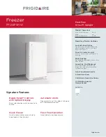
FFU14FC4CW1
Brand: Frigidaire Pages: 7
FFU14F5H W
Brand: Frigidaire Pages: 2

FFU14C2AW0
Brand: Frigidaire Pages: 2

FFU14FC4CW
Brand: Frigidaire Pages: 7
FFU14F3AW3
Brand: Frigidaire Pages: 7

FFU14C3AW1
Brand: Frigidaire Pages: 7

FFU14C3AW
Brand: Frigidaire Pages: 7

FFU14FC4AW3
Brand: Frigidaire Pages: 7

FFU14F3AW
Brand: Frigidaire Pages: 7

FFU14F9G
Brand: Frigidaire Pages: 8

FFU14FC2CW
Brand: Frigidaire Pages: 7

FFU14F9GW
Brand: Frigidaire Pages: 7

FFU14FC4CW0
Brand: Frigidaire Pages: 7

FFU14FC3AW
Brand: Frigidaire Pages: 7


