background image

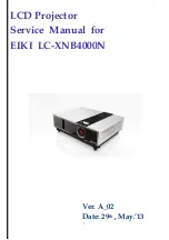
LCD Projector


Service  Manual  for   

EIKI  LC-XNB4000N 


Ver. A_02


Date: 29

th

 , May.’13 

Summary of Contents for LC-XNB4000N

Page 1: ...1 LCD Projector Service Manual for EIKI LC XNB4000N Ver A_02 Date 29th May 13...

Page 2: ...ce 7 Software Firmware Upgrade Process 7 Update USB Firmware Procedure 12 Disassembly Assembly 16 Exploded Chart 17 Disassembly Indication 28 Level 2 Structure Diagram 43 Block Diagram 44 Troubleshoot...

Page 3: ...and test equipment for servicing 6 Never assume the product s power is disconnected from the mains power supply Check that it is disconnected before opening the product s cabinet 7 Modules containing...

Page 4: ...cal component s heat Key Features High Brightness 4000ANSI Lumens Designed for tough environments Easy Installation maintenance even when ceiling mounted Built in auto detector sensor Side change filt...

Page 5: ...6 Packing...

Page 6: ...7...

Page 7: ...d already been installed Microsoft NET Framework Version 2 0 If not please visit Microsoft website to download and install Picture 1 Picture 1 2 If you are WinXP and Win2000 user but can not install M...

Page 8: ...Version 2 0 had been installed completely then open the firmware folder Execute the ED_UpgradeFlasher exe Picture 3 Picture 3 4 After execute the ED_UpgradeFlasher exe Picture 3 you will see the windo...

Page 9: ...10 5 After pressing Connect Button please press Flash Mode Button as following Picture 5 Picture 5 6 The Pixel Work Image Processor SDK Flasher Upgrader will process automatically Picture 6...

Page 10: ...When the firmware is flashed completely you will see the below picture Picture 7 please press OK to quit this program Picture 7 8 If you need to re flash another projector please repeat Item 4 to 7 s...

Page 11: ...utlet with the power cable Connect RS232 cable from the computer to the projector s RS232C port Connect mini USB cable from the computer to the projector s mini USB port 2 Launch EDI_Serial_one exe 3...

Page 12: ...13 4 Go to Flash USB LAN Display tab 5 Click Flash mode button 6 Clicked Exit 7 Launch the application program of ActionsMPUpdate exe 8 Wait for USB device Actions USB Device appeared...

Page 13: ...14 9 Clicked Update Tab 10 focus Linux update item on Firmware button then click and select the file where you put and need to update...

Page 14: ...15 11 Clicked Download to update 12 Wait for download process Done...

Page 15: ...Cover Main board IO Optical Engine Power Ballast Module Exhaust Duct Lamp Inlet Duct Lamp PSC Guide Case Bottom Lens Cover and CMOS 2 Disassembly Indication Top Cover PCBA Main board Optical Engine Po...

Page 16: ...rt Item Parent Name Parent Number A ASSY_TOP_COVER B MB ASM 23010317 C ASSY_OPTICAL_ENGINE D ASSY_POWER_BALLAST E ASSY_EXHAUST_DUCT F LAMP_ASSY 23040039 G ASSY_INLET_DUCT H ASSY_LAMP_DUCT and Fan I AS...

Page 17: ...D GP 13220623 1 2 Dress Plate Case Top GP 13220650 1 3 Door Lamp GP 13220277 1 4 Cover Filter IR GP 13220282 1 5 IR Remote Cover GP 13220184 1 6 Inlet Door Sponge Filter GP 13220278 1 7 Keypad GP 1322...

Page 18: ...23010314 1 2 Connect Plate GP 13210169 1 3 Plate IO GP 13210168 1 4 Speaker_Line GP 13680010 1 5 Speaker Sponge GP 13340161 2 6 Aluminum Foil GP 13310045 1 7 COPPER_BOSS GP 13270005 6 8 SCREW GP 13270...

Page 19: ...13220293 1 3 LAMP_HOUSING_TOP GP 13220285 1 4 Lamp Housing BTM GP 13220284 1 5 Thermal Wire GP 13630015 1 6 Zoom Ring GP 13220295 1 7 Focus Ring GP 13220294 1 8 Sponge_lens GP 13340162 1 9 Cable Ball...

Page 20: ...1 2 Mylar Ballast GP 13290036 1 3 Ballast GP 13670054 1 4 Power Supply GP 13670049 1 5 Mylar Power GP 13290035 1 6 Case Power GP 13210104 1 7 Sponge PB Case GP 13340178 1 8 Aluminum Foil GP 13310040 1...

Page 21: ...22 Exploded Chart Exhaust Duct Item Part Name Part Number Q ty E ASSY_EXHAUST_DUCT 1 1 Duct Exhaust GP 13220290 1 2 Fan GP 13260026 1...

Page 22: ...0124 1 4 Explosion mesh 0 8 GP 13210123 1 5 Clip Lamp Top GP 13210152 1 6 Clip Lamp Bottom GP 13210153 1 7 Lamp Fin Philips GP 13210154 1 8 Lamp GP 13080016 1 9 Lamp Housing Slide GP 13220654 1 10 Cas...

Page 23: ...13340152 1 2 Frame Sponge Filter GP 13220289 1 1 2 Filter Assy 23390008 Filter Inlet Frame Sponge Filter 3 Filter Noise GP 13340149 1 4 Mesh GP 13210120 1 5 Inlet Duct 1 GP 13220489 1 6 Aluminum Foil...

Page 24: ...rt Lamp PSC Guide Item Part Name Part Number Q ty H ASSY_LAMP_DUCT and Fan 1 1 Duct1 Lamp GP 13220628 1 2 Duct2 Lamp GP 13220287 1 3 Inlet Blower Lamp GP 13260027 1 4 SCREW GP 13270042 1 5 Fin of Duct...

Page 25: ...18 1 5 Gasket GP 13290068 1 6 Aluminum Foil GP 13310042 1 7 Gasket GP 13290052 1 8 Gasket GP 13290069 1 9 Inlet Duct 2 GP 13220656 1 10 Handle Guide Pin GP 13210091 1 11 Adjust Foot A GP 13220092 2 12...

Page 26: ...27 Exploded Chart Case Bottom 2 Item Part Name Part Number Q ty I ASSY_CASE_BOTTOM 1 1 Inlet Blower Panel GP 13260028 1 2 Sponge BB down GP 13340151 1 3 Sponge Gate GP 13340148 1...

Page 27: ...28 Disassembly Indication Top Cover Disassembly a Pull off the lamp cover b Loose 2 screws and pull lamp module out c Pull up the filter wall...

Page 28: ...29 d Remove the wall e Remove the filter case and filter sponge...

Page 29: ...30 f Remove 2 screws on the I O board h Turn to bottom side and remove 5 screws on the bottom case...

Page 30: ...31 i Remove the top cover j Done...

Page 31: ...32 Disassembly Indication PBCA Disassembly a Remove the cable wire b Remove 6 screws on the PCBA module...

Page 32: ...33 c Remove the PCBA d Done...

Page 33: ...34 Disassembly Indication Optical Engine Disassembly a Remove 1 screw to remove the exhaust fan module b Remove the duct cover...

Page 34: ...35 c Remove 2 screws to remove the lamp blower d Remove 5 screws which fixed the optical engine...

Page 35: ...36 e Remove the optical engine f Remove one screw and cable...

Page 36: ...37 g Done...

Page 37: ...38 Disassembly Indication Power Ballast module Disassembly a Remove 2 screws and remove the AC filter b Remove the cable which AC filter to Power...

Page 38: ...39 c Remove 3 screws to remove the power ballast module d Done...

Page 39: ...40 Disassembly Indication Inlet duct module Disassembly a Remove the Aluminum tape b Remove 3 screws of the air duct and remove it...

Page 40: ...41 c Remove 4 screws of the panel duct to remove the duct and blower d Done...

Page 41: ...42 Disassembly Indication Other components Disassembly a Shielding Mylar sponge aluminum tape and two gaskets remove it directly b Remove the security bar lamp door switch and adjust foots...

Page 42: ...ization circuit Lamp lit feedback circuit and power control circuit The Image Processor chipset is PW190 also known as Scaler which indicate its main function expand or down size the digital picture f...

Page 43: ...44...

Page 44: ...45...

Page 45: ...46...

Page 46: ...47...

Page 47: ...48...

Page 48: ...49...

Page 49: ...50...

Page 50: ...51...

Page 51: ...52...

Page 52: ...53...

Page 53: ...54 G G G G...

Page 54: ...55...

Page 55: ...n Service mode Hidden from end users for Service Repair Center only 1 Press button sequentially POWER AUTO MENU Please press as quickly as possible after start up logo disappears KEYSTONE LEFT RIGHT U...

Page 56: ...57 Service mode Calibration 2 You will see the image as below a Page System Inf b Page Set Up 01...

Page 57: ...tilation area A 4 Temp 2 Temperature of projector panel A 5 Temp 3 Temperature of projector lamp A 6 Lamp Timer The end user operation hours which can be reset A 7 Lamp Total Timer The total system op...

Page 58: ...N Reset PIN code reset B 5 Logo Memory Reset Logo image is erased on the flash ram B 6 Unit Timer Reset Unit time is the total working time period of PCBA which is for internal usage B 7 Filter Timer...

Page 59: ...60 Service mode Calibration C Lamp Timer Reset a Select Lamp Timer Reset b Press right key c Confirmation information shows up as fig 4 d Select Yes e Press right key...

Page 60: ...n as fig 7 fig 7 b Select OSD Picture Display mode Nature mode as fig 8 fig 8 c Enter Service mode Press POWER AUTO MENU on keypad d Select page System Inf e Select C B Calibration fig 9 f Press right...

Page 61: ...if you activate the PIN Lock Protection it is highly recommended that you write down the PIN code and keep it in a safe place SECURITY PIN lock protection Off On 1 On 2 Off Turn off PIN lock protectio...

Page 62: ...ode 1 Activate the OSD menu and go to SECURITY Modify PIN 2 Press Right button to enter PIN layer 3 Enter the original PIN code If the PIN is correct system will allow you to change a new PIN code If...

Page 63: ...other digits please press to go to next row vi In case you entered a wrong digit select backspace to delete the wrong digit you entered vii Once all four digits of the PIN been entered select to conf...

Page 64: ...e PIN lock protection function is on the system will display the PIN lock number entering screen after lamp is on After user s three times wrong PIN number input system switches off the lamp 3 While s...

Page 65: ...of the random number array and the n PIN number is generated as the remainder of 1000 divides the internal timer counter of Pixelworks scalar chip 6 User needs to pass the magic number to the distrib...

Page 66: ...environment set the filter timer longer For dirty environment set the filter timer shorter Filter warning When the operation time reached the timer set a warning message will appears on the screen to...

Page 67: ...15 15 2 Pin Number Define Pin NO Signal name Connection 1 R signal Input R 2 G signal Input G Sync On G 3 B signal Input B 4 N C N C 5 GND GND 6 R return GND GND 7 G return GND GND 8 B return GND GND...

Page 68: ...nc Negative 4 Input level Video signal 1 0V 0 2V p p 75 terminate NRZ S Video signal 1 S Video Connections and Connector 2 Pin Number Define Pin NO Signal name Connection 1 Y signal return GND GND 2 C...

Page 69: ...5 Vertical 15 Command Code List Custom Code 0x6A Data Code Item Value Command Description Code1 0x00 Power Code2 0x11 Input Code3 0x0b Menu Right Volume Up Code4 0x0f Menu Left Volume down Code5 0x14...

Page 70: ...e are two types of command functional execution commands and status read commands 3 Response for status read command after accepting has different characters Example A Functional execution command Pow...

Page 71: ...41 0D VOLUME C1D 43 31 44 0D MENU C30 43 33 30 0D UP C31 43 33 31 0D DOWN C32 43 33 32 0D LEFT C33 43 33 33 0D RIGHT C34 43 33 34 0D MUTE C0B 43 30 42 0D MUTE ON C0C 43 30 43 0D MUTE OFF C43 43 34 33...

Page 72: ...O 004 YPbPr CR2 43 52 32 0D LAMP TIMER STATUS STATUS feedback X XXX XXX Mins Lamp usage timer in minutes CR3 43 52 33 0D FILTER TIMER STATUS STATUS feedback X XXX XXX Mins Filter usage timer in minute...

Page 73: ...decimal CR carriage return is 0x0D in hexadecimal At standby mode only these commands can be accepted All the above commands are available at normal operation mode except the POWER ON command The temp...

Reviews: