Eickemeyer MAGIC 500 PLUS, User Manual
The Eickemeyer MAGIC 500 PLUS is a user-friendly device designed to simplify your tasks. Unlock its full potential by accessing the comprehensive User Manual, available for free download at manualshive.com. This manual offers step-by-step instructions which can enhance your experience and maximize the benefits of this amazing product.
Share
Download


Reviews:
No comments
Related manuals for MAGIC 500 PLUS

Sprint
Brand: Velopex Pages: 25

IT 4715
Brand: Leuze Pages: 15

WideTEK 25-600
Brand: Image Access Pages: 101

FILM 2 PC
Brand: ION Pages: 1

Granit XP 1990i
Brand: Honeywell Pages: 11
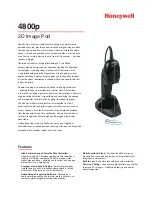
4800p
Brand: Honeywell Pages: 2

Stratos MS2400
Brand: Honeywell Pages: 2

6300dpm
Brand: Honeywell Pages: 2

8620
Brand: Honeywell Pages: 13

Voyager XP 1470g Series
Brand: Honeywell Pages: 16

HH480
Brand: Honeywell Pages: 36

HH400
Brand: Honeywell Pages: 36

StratosH MS2321
Brand: Honeywell Pages: 62

4850DR
Brand: Honeywell Pages: 34

HH450
Brand: Honeywell Pages: 36

HF680
Brand: Honeywell Pages: 66

4022
Brand: Honeywell Pages: 239

Voyager XP 1470
Brand: Honeywell Pages: 246


