1
RELAY BASES
for Smoke, Heat & Carbon Monoxide Alarms
Instruction Manual
Read and retain carefully for as long as the product is being used.
It contains vital information on the operation and installation of
your product. This instruction manual should be regarded as part
of the product.
If you are just installing this product, this manual must be given
to the householder. The manual is to be given to any subsequent
user.
1. Introduction
The Ei128R & Ei128RBU Relay Bases switch a relay upon receipt
of an alarm signal from a hardwire interconnection with a mains
powered Ei Alarm. The electrically isolated relay contacts can be
used for many applications such as shutting off the mains supply
to boilers, triggering panels, etc. The Relay Bases are powered by
230VAC mains - with the Ei128RBU model having recharbeagle
back-up cells.
The Relay Bases are normally installed directly underneath an
Easi-fit Alarm base but can also be sited separately.
As supplied the relay operates continuously (e.g. it switches when
one of the Alarms sounds and switches back when it receives the
alarm cancel signal). When the slide switch is moved to the pulse
‘P’ position (see figures 1a & 1b) the relay will switch when the
Alarm sounds but will automatically switch back after 5 seconds.
This is commonly used with warden call systems where only
momentary short circuit signalling is required.
Both the Ei128R and Ei128RBU can be used in 230VAC and low
voltage applications with the Ei128RBU being best suited for low
voltage applications.
2. Overview
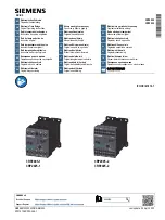
Models:
Ei128R
Ei128RBU
LOCATION FOR
SCREWS
Cover