Ecoflam BLU 1000.1 PR, Manual
The Ecoflam BLU 1000.1 PR is a high-performance industrial burner. For optimal operation, make sure to refer to the comprehensive user manual available for free download on our website. Download the manual today to ensure smooth and efficient functioning of your Ecoflam burner.
Share
Download


Reviews:
No comments
Related manuals for BLU 1000.1 PR

Bentone BG 300-2
Brand: Enertech Pages: 28

TBG 55
Brand: baltur Pages: 74

KU-HP1700-WH
Brand: Kudu Pages: 8

HMG
Brand: Hansa-electronic Pages: 5

Dual Fuel Range
Brand: Wolf Pages: 32

LMB TWIN 600
Brand: Lamborghini Caloreclima Pages: 56

200 SGR
Brand: Campingaz Pages: 54

Grand Turbo BGTSB15ALP
Brand: Barbeques Galore Pages: 21

AirHeat AH series
Brand: Eclipse Pages: 14

P75A
Brand: Unigas Pages: 76

TP-12/G
Brand: Diamond Pages: 15

BTL 4P
Brand: baltur Pages: 60

PSRKIT11
Brand: TriangleTube Pages: 4
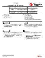
INSRKIT100
Brand: TriangleTube Pages: 9

M64482
Brand: Carolina Cooker Pages: 28

M78097
Brand: Carolina Cooker Pages: 28

Integra Balanced
Brand: Cast Tec Pages: 16

863 Series
Brand: Outland Firebowl Pages: 12


