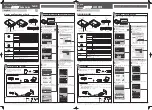
background image


E70-433T14S2 User Manuel 

CC1310 433MHz SMD Wireless Module 


Summary of Contents for E70-433T14S2

Page 1: ...E70 433T14S2 User Manuel CC1310 433MHz SMD Wireless Module ...

Page 2: ...6 2 RSSI MODE MODE 0 12 6 3 CONTINUOUS MODE MODE 1 13 6 4 SUB PACKAGE MODE MODE 2 13 6 5 CONFIGURATION MODE MODE 3 14 6 6 WAKE UP MODE MODE 4 14 6 7 CONFIGURATION MODE MODE 5 14 6 8 POWER SAVING MODE MODE 6 15 6 9 SLEEP MODE MODE 7 15 7 INSTRUCTION FORMAT 15 7 1 DEFAULT PARAMETER 16 7 2 READING OPERATING PARAMETERS 16 7 3 READING VERSION NUMBER 16 7 4 RESET INSTRUCTION 16 7 5 PARAMETER SETTING INS...

Page 3: ...Technology Co Ltd E70 433T14S2 user manual Copyright 2012 2019 Chengdu Ebyte Electronic Technology Co Ltd 2 14 1 ANTENNA RECOMMENDATION 24 14 2 ANTENNA SELECTION 25 15 PACKAGE FOR BATCH ORDER 25 REVISION HISTORY 26 ABOUT US 26 ...

Page 4: ...users can also conduct secondary development Accordingly 1 2 Features Communication distance tested is up to 1 5km Maximum transmission power of 25mW software multi level adjustable Super low receiving current of 8mA Small size 14x20mm Support RSSI Development based on CC1310 with dual core ARM Support the global license free ISM 433MHz band Support air date rate of 2 5kbps 168kbps Low power consu...

Page 5: ...sk of burning down Operating temperature 40 85 Industrial design Operating frequency MHz 425 450 5 Support ISM band Power consumption Transmitting current mA 36 Instant power consumption Receiving current mA 8 Turn off current μA 1 2 Software is shut down Max Tx power dBm 13 6 14 0 15 3 Receiving sensitivity dBm 107 108 109 Air data rate is 2 5kbps Air data rate bps 2 5k 2 5k 168k Controlled via u...

Page 6: ...A_EN Reserved pin Internal MCU controlled LNA pin valid in high level connect to pin 44 12 LNA_EN Reserved pin Internal MCU controlled PA pin valid in high level connect to pin 45 13 M2 Input M2 M1 M0 jointly decide the 8 working modes An external 1k protective resistor shall be connected in series when in use 14 RESET Input Reset pin valid in low level 15 GND Ground Ground electrode 16 AUX output...

Page 7: ...TXD pin It can be configured as open drain or high pull input please refer to Parameter setting An external 1k protective resistor shall be connected in series when in use 21 M1 Input M2 M1 M0 jointly decide the 8 working modes An external 1k protective resistor shall be connected in series and a 1M pull up resistor shall be added when in use Cannot be floated it can be grounded when not used 22 M...

Page 8: ...r manual Copyright 2012 2019 Chengdu Ebyte Electronic Technology Co Ltd 7 4 Connect to MCU No Description STM8L MCU 1 The UART module is TTL level please collect with MCU 2 For some MCU works at 5VDC it may need to add 4 10K pull up resistor for the TXD AUX pin ...

Page 9: ...echnology Co Ltd 8 5 Function description 5 1 Fixed transmission 5 2 Broadcasting transmission 5 3 Broadcasting address For example Set the address of module A as 0xFFFF or 0x0000 and the channel as 0x04 When module is the transmitter transparent transmission all modules under channel 0x04 will receive the data the ...

Page 10: ...work as per the operating mode combined by M1 and M0 Therefore users need to wait the AUX rising edge as the start of module s normal work 5 6 AUX description AUX Pin can be used as indication for wireless send receive buffer and self check It can indicate whether there are data that are not sent yet via wireless way or whether all wireless data has been sent through UART or whether the module is ...

Page 11: ...mstance it may cause overtime when the module is waiting for the user data or transmitting wireless sub package When AUX 1 it does not mean that all the UART data of the module have been transmitted already perhaps the last packet of data is still in transmission 5 6 3 Configuration procedure of module Only happened when power on resetting or exiting sleep mode ...

Page 12: ...eceiving is not available under this mode Preamble code will be added proactively before transmission to wake up the receiver under mode 6 5 Configuration mode Same as Mode 3 1 0 1 6 Power saving mode 1 1 0 UART closes Wireless works at WOR power saving mode Multiple time grades can be configured Transmission is not available under this mode It can be woken up by transmitter under mode 4 to achiev...

Page 13: ... working time save power Likewise this feature can be used in any mode switch The module will start to work in new mode within 1ms after completing present mode task which enables the user to omit the procedure ofAUX inquiry and switch mode swiftly For example when switching from transmitting mode to receiving mode the user MCU can go dormancy before mode switch using external interrupt function t...

Page 14: ...3 The addresses and baud rates must be same on both receiver and transmitter 4 In continuous mode both transmitter and receiver must be same model For example E70 868T14S and E70 868T30S cannot communicate in continuous mode 6 4 Sub package Mode Mode 2 Status M0 0 M1 1 M2 0 Transmitting Wireless data transmission is available Receiving Wireless data receiving is available Baud rate air data rate U...

Page 15: ... is not available Baud rate air data rate Under this mode the baud rate and air data rate are independent both receiver and transmitter can have different baud rate but same air data rate Advantage It can wake up the receiver under mode 6 wake up code will be added automatically before transmitting the code number depends on the wake up time Disadvantage The transmission time is long only applicab...

Page 16: ...gh serial port and then enters WOR status again which can save power consumption significantly Disadvantage Transmission is not available under this mode the module must be switched to other mode for data transmission Applications Applicable for those devices which have requirement on power consumption and need to receive data Note It can only receive the data sent from the transmitter under mode ...

Page 17: ...ruction format Description C1 C1 C1 In configuration mode M0 1 M1 1 M2 0 User gives the module instruction HEX format C1 C1 C1 Module returns the present configuration parameters For example C0 00 00 18 4E 1C 7 3 Reading Version Number Instruction format Description C3 C3 C3 In configuration mode M0 1 M1 1 M2 0 User gives the module instruction HEX format C3 C3 C3 Module returns its present versio...

Page 18: ... UART baud rate can be different between communication parties The UART baud rate has nothing to do with wireless transmission parameters won t affect the wireless transmit receive features 0 0 0 1200 0 0 1 2400 0 1 0 4800 0 1 1 9600 Default 1 0 0 19200 1 0 1 38400 1 1 0 57600 1 1 1 115200 2 1 0 Air data rate bps The lower the air data rate the longer the transmitting distance better anti interfer...

Page 19: ...e up time on both modules shall be the same 0 0 0 500ms 0 0 1 1000ms Default 0 1 0 1500ms 0 1 1 2000ms 1 0 0 2500ms 1 0 1 3000ms 1 1 0 3500ms 1 1 1 4000ms 3 FEC switch After turn off FEC the actual data transmission rate increases while anti interference ability decreases Also the transmission distance is relatively short Both communication parties must keep on the same pages about turn on or turn...

Page 20: ...8 Parameter Setting When the module is in Mode 3 M0 1 M1 1 M2 0 or Mode 5 M0 1 M1 0 M2 1 the parameter can be set by instruction or software in PC Please visit www cdebyte com to download the software 9 Secondary Development E70 series have built in CC1310 SoC chip Users can conduct the development according to pin description below Meanwhile Ebyte can develop the customized software for customers...

Page 21: ...put Output MCU GPIO 13 DIO_5 Input Output MCU GPIO 14 RESET Input Output MCU GPIO 16 DIO_4 Input Output MCU GPIO 17 DIO_3 Input Output MCU GPIO 18 TCKC Input JTAG TCKC 19 TMSC Input JTAG TMSC 20 DIO_2 Input Output MCU GPIO 21 DIO_1 Input Output MCU GPIO 22 DIO_0 Input Output MCU GPIO 24 ANT Antenna 50Ω characteristic impedance 9 1 Download Program Key word Notes Input program The module is SOC wit...

Page 22: ...st be avoided under the module If it is necessary to pass through the module assume that the module is soldered to the Top Layer and the copper is spread on the Top Layer of the module contact part well grounded it must be close to the digital part of the module and routed in the Bottom Layer Assuming the module is soldered or placed over the Top Layer it is wrong to randomly route over the Bottom...

Page 23: ...a is near metal object or put in a metal case Power register was set incorrectly air data rate is set as too high the higher the air data rate the shorter the distance The power supply low voltage under room temperature is lower than 2 5V the lower the voltage the lower the transmitting power Due to antenna quality or poor matching between antenna and module 11 2 Module is easy to damage Please ch...

Page 24: ...n96 5 Ag3 Cu0 5 Preheat Temperature min Tsmin 100 150 Preheat temperature max Tsmax 150 200 Preheat Time Tsmin to Tsmax ts 60 120 sec 60 120 sec Average ramp up rate Tsmax to Tp 3 second max 3 second max Liquidous Temperature TL 183 217 Time tL Maintained Above TL 60 90 sec 30 90 sec Peak temperature Tp 220 235 230 250 Average ramp down rate Tp to Tsmax 6 second max 6 second max Time 25 to peak te...

Page 25: ...enna Guidance 14 1 Antenna recommendation The antenna is an important role in the communication process A good antenna can largely improve the communication system Model No Type Frequency Hz Interface Gain dBi Height Cable Function feature TX433 NP 4310 Soft PCB antenna 433M SMA J 2 43 8 9 5mm Built in flexibility FPC soft antenna TX433 JW 5 Rubber antenna 433M SMA J 2 50mm Flexible omnidirectiona...

Page 26: ...ngdu Ebyte Electronic Technology Co Ltd E70 433T14S2 user manual Copyright 2012 2019 Chengdu Ebyte Electronic Technology Co Ltd 25 14 2 Antenna selection IPEX Default Stamp hole 15 Package for batch order ...

Page 27: ...aa 1 20 2018 05 24 content updating Huaa 1 21 2018 07 20 name change Huaa 1 30 2018 10 29 module separating Huaa 1 40 2019 03 20 Content updating Ray About us Technical support support cdebyte com Documents and RF Setting download link www ebyte com Thank you for using Ebyte products Please contact us with any questions or suggestions info cdebyte com Fax 028 64146160 Web www ebyte com Address Inn...

Reviews: