Ebyte E49-400T20S, User Manual
The Ebyte E49-400T20S comes with a comprehensive User Manual, providing detailed instructions for smooth operation. This essential manual is available for free download at manualshive.com, ensuring easy access to essential information about the product's features, settings, and troubleshooting tips.
Share
Download


Reviews:
No comments
Related manuals for E49-400T20S

JBL QUANTUM TWS
Brand: Harman Pages: 25

JBL Quantum 810 Wireless
Brand: Harman Pages: 21

JBL ENDURANCE PEAK
Brand: Harman Pages: 14

Base Station
Brand: Raymarine Pages: 12

DWL-AG700AP - AirPlus AG - Wireless Access...
Brand: D-Link Pages: 59

DWL-3260AP - AirPremier - Wireless Access...
Brand: D-Link Pages: 57

WP-300N
Brand: Cerio Pages: 13

WA2200 Series
Brand: H3C Pages: 41

LigoPTP 5-23 UNITY
Brand: LogoWave Pages: 14

MWI-5000
Brand: MeshLinx Pages: 94

WAP2000
Brand: Linksys Pages: 40
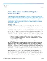
880G Series
Brand: Cisco Pages: 9

USC 3330
Brand: Cisco Pages: 12

Small Business WAP551
Brand: Cisco Pages: 4

Linksys WRT120N
Brand: Cisco Pages: 35

WUMC710
Brand: Cisco Pages: 17

VEN501
Brand: Cisco Pages: 2

Linksys WRT54GS2
Brand: Cisco Pages: 6


