Ebyte E22-230T30D, User Manual
Introducing the Ebyte E22-230T30D, a cutting-edge device offering seamless connectivity. Discover its full potential by accessing the comprehensive User Manual available for free download at manualshive.com. This manual will guide you through setup and operation, ensuring you unlock the true power of your Ebyte E22-230T30D effortlessly.
Share
Download


Reviews:
No comments
Related manuals for E22-230T30D

BT402
Brand: Atatech Pages: 2

ZGB10A
Brand: CardAccess Pages: 12

MiFi 8000
Brand: Global Telecom Pages: 5

Elite HP250
Brand: J.Burrows Pages: 10

PE-8074
Brand: 7links Pages: 170

Pepwave Surf SOHO
Brand: peplink Pages: 151

BR-622nC
Brand: Edimax Pages: 147
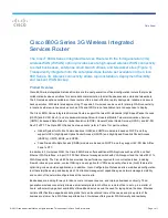
880G Series
Brand: Cisco Pages: 9

USC 3330
Brand: Cisco Pages: 12

Small Business WAP551
Brand: Cisco Pages: 4

Linksys WRT120N
Brand: Cisco Pages: 35

WUMC710
Brand: Cisco Pages: 17

VEN501
Brand: Cisco Pages: 2

Linksys WRT54GS2
Brand: Cisco Pages: 6

Linksys E2100
Brand: Cisco Pages: 10

Linksys SE1500
Brand: Cisco Pages: 2

Linksys WRT54G3G
Brand: Cisco Pages: 3

Linksys WRT320N
Brand: Cisco Pages: 54


