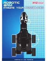
background image

Contains


Small 

Pieces

Arm

User manual

Arm Robot


Electronics and programming Kit:

Arm Robot and double joystick gamepad

Summary of Contents for Arm Robot

Page 1: ...Contains Small Pieces Arm User manual Arm Robot Electronics and programming Kit Arm Robot and double joystick gamepad...

Page 2: ...LANGUAGE INDEX Choose the language SPANISH FRENCH ITALIAN ENGLISH DEUTSCHLAND...

Page 3: ...ndice Interactivo 3 ARM ROBOT MANUAL...

Page 4: ...pen Source puedes encontrar manuales y ejercicios para aprender a utilizar el 100 de las posibilidades del Arm Robot de manera gratuita Adem s es compatible con distintos softwares de programaci n por...

Page 5: ...5 ARM ROBOT MANUAL M3 25 M3 10 M3 8 M3 6 M2 5 TUERCA M3 X4 X18 X18 X7 X5 X26...

Page 6: ...JOYSTICK CABLE USB TIPO A USB TIPO B PLACA BUILD CODE UNO PLACA SENSOR 3 CABLES PUENTE MACHO HEMBRA 8 CABLES PUENTE HEMBRA HEMBRA PLACA MANDO Servomotor y sus piezas Requieres un destornillador de est...

Page 7: ...de doble joystick p 33 Conexiones El Arm Robot viene con una placa Build Code UNO sobre la cual se incrusta la placa sensor Build Code la cual facilita las conexiones de los 4 Servomotores y 2 joysti...

Page 8: ...rr n que debes retirar cuidadosamente antes de comenzar el montaje 3 Utiliza las herramientas adecuadas para extraer las partes m s peque as que se han de desechar por ejemplo los agujeros para los to...

Page 9: ...9 ARM ROBOT MANUAL Ubicaci n de las piezas en las placas troqueladas la estructura del brazo BASE1 A1 A2 A3 A4 A5 A6 A7 BASE2...

Page 10: ...10 ARM ROBOT MANUAL C1 C2 C3 C3 C3 C3 C3 C4 C5 C6 C7 C8 C9 C10 C11 C12 D1 D1 D1 D1 D2 D3 D3 D3 D4 D5 D6 C3...

Page 11: ...1 seg n se muestra Coloca los tornillos M3 10 y M3 25 en su posici n Aprieta firmemente las tuercas en los tornillos M3 10 NOTA En los tornillos M3 25 deja una holgura F1_A para poder apretar las tuer...

Page 12: ...uidado al fijar los tornillos M3 8 a la BASE2 Deja una holgura sim trica F2_B a ambos lados y la rosca de los tornillos no debe sobresalir de la BASE2 M3 8 X2 D1 BASE2 Servomotor Nota No siempre utili...

Page 13: ...BASE2 con relaci n a la BASE1 el rotor del Servomotor debe quedar hacia arriba Une ambas bases mediante los tornillos M3 25 Aprieta las tuercas a la BASE1 para fijar la estructura firmemente F3_B Resu...

Page 14: ...M3 8 X2 X1 D1 A5 D6 La pieza para fijar el pivote al eje del rotor del Servomotor est n incluidas en el kit de montaje de los Servomotores S3 C digo de identificaci n del SERVO para las conexiones a l...

Page 15: ...QUE ACABA DE ADOPTAR 4 7 Vuelve a insertar el brazo m vil D6 en la posic n inicial y en el ngulo que muestra el gr fico 4 8 Fija el brazo m vil D6 al eje del rotor utilizando el tornillo m s peque o q...

Page 16: ...en el kit de montaje de los Servomotores M3 8 X2 D1 A6 PASO 5 Monta la tapa izquierda del CUERPO con el Servomotor y su pivote articulado S2 C digo de identificaci n del SERVO para las conexiones a la...

Page 17: ...ento correcto de los Servomotores 5 4 Gira el brazo m vil D5 sujeto al SERVO HASTA EL TOPE DE MOVIMIENTO y en el sentido de las manecillas del reloj 5 5 RESULTADO 5 6 Retira el brazo m vil D5 del eje...

Page 18: ...M3 6 C8 A1 D4 A3 PASO 6 Monta la base de la estructura rotatoria que soporta el brazo articulado Nota Ten en cuenta los agujeros de la pieza D4 para su correcta colocaci n NO son sim tricos X2 X1 PIEZ...

Page 19: ...que se indica en el esquema Ten en cuenta que un lado es m s corto que otro indicado con la linea de puntos Lee antes de comenzar Para evitar errores de montaje y solamente con car cter explicativo e...

Page 20: ...los tornillos y tuercas necesarios para el montaje del CUERPO 7 5 7 6 Esquema Elementos de las UNI NES M3 90 PIEZAS NECESARIAS M3 10 A7 C1 X4 X4 TUERCA M3 Importante En la fijaci n de este montaje se...

Page 21: ...21 ARM ROBOT MANUAL RESULTADO Nota Este es el resultado final del CUERPO con todos los elementos que incluye Servomotores pivotes cables etc 7 7...

Page 22: ...salen de las placas y que se introducen a 90 PASO 1 Encaja la tuerca M3 dentro de la abertura en forma de cruz Esto evita que la tuerca gire al introducir el tornillo PASO 2 Puedes sujetar la tuerca c...

Page 23: ...6 M3 6 M3 8 X2 X1 D3 D2 C10 D3 RESULTADO Nota Las piezas que componen este montaje son m viles Deja holgura en las uniones para facilitar el movimiento PIEZAS NECESARIAS PASO 8 Monta el brazo articula...

Page 24: ...AL M3 6 M3 6 M3 8 X2 X1 X1 C12 D3 X1 C3 M3 8 M3 6 Antes de comenzar este paso Rota EL CUERPO 180 para acceder al punto de vista de la zona de montaje Zona de montaje Zona de montaje PIEZAS NECESARIAS...

Page 25: ...C9 PASO 9 9 1 9 2 9 3 9 4 Monta los elementos que conforman la pinza de sujeci n S4 C digo de identificaci n del SERVO para las conexiones a la placa PIEZAS NECESARIAS Servomotor Nota No siempre utili...

Page 26: ...X2 X1 C3 C3 C11 C6 C7 La pieza para fijar el pivote al eje del rotor del Servomotor est n incluidas en el kit de montaje de los Servomotores PIEZAS NECESARIAS PIEZAS NECESARIAS 9 7 Gira los brazos que...

Page 27: ...1 sujeto al SERVO HASTA EL TOPE DE MOVIMIENTO en el sentido contrario a las manecillas del reloj 9 10 Fija el brazo m vil C11 al eje rotor del SERVO en la posici n indicada utilizando el tornillo pequ...

Page 28: ...os tornillos deja una holgura suficiente que permita el desplazamiento de las partes m viles El tercer tornillo T3 M3 8 debes atornillarlo en la misma posici n que el tornillo T2 pero en el lado opues...

Page 29: ...la BASE2 y el brazo rob tico Sit a el brazo rob tico sobre la BASE2 11 1 Coloca la pieza D1 en la posici n indicada Esta pieza evita la fricci n entre la BASE2 y el brazo robot 11 2 Gira el brazo robo...

Page 30: ...rrecto de los Servomotores 11 3 Gira el brazo robot HASTA EL TOPE DE MOVIMIENTO y en el sentido de las manecillas del reloj 11 6 RESULTADO 11 4 Retira la estructura m vil del eje rotor del SERVO DEJAN...

Page 31: ...31 ARM ROBOT MANUAL PASO 12 Fija la estructura m vil a la BASE2 mediante tornillo TORNILLO Servomotor X1 PIEZAS NECESARIAS...

Page 32: ...NUAL PASO 13 Coloca la placa Build Code UNO sobre la BASE1 haciendo coincidir los agujeros para los tornillos Utiliza las tuercas M3 para fijar la placa PLACA BUILD CODE UNO RESULTADO Tuerca M3 X3 PIE...

Page 33: ...NUAL PLACA SENSOR RESULTADO PASO 14 Coloca la placa sensor sobre la placa Build Code UNO haciendo coincidir los pines de contacto Utiliza los agujeros para los tornillos como referencia de posici n PI...

Page 34: ...ks a la placa mando utilizando los tornillos y las tuercas M3 Los pines de contacto de los joysticks deben quedar orientados hacia afuera J2 C digo de identificaci n del joystick para las conexiones a...

Page 35: ...AL Servomotor S3 Servomotor S4 Servomotor S2 Servomotor S1 SERVO CONEXI N COLOR S1 6 Rojo S2 9 Rojo S3 10 Rojo S4 11 Rojo Nota Usa los cables puente ma cho hembra para alargar la conexi n del Servomot...

Page 36: ...A1 S A3 Verde SW CONECTAR LOS JOYSTICKS Utiliza los cables puente hembra hembra para conectar los joysticks Recuerda que las conexiones de los joysticks est n representadas en la placa sensor con el c...

Page 37: ...rueba que Arduino o el software gr fico de programaci n por bloques compatible est n correctamente configurados Comprueba que la secci n de placas est configurada para trabajar con Arduino UNO y que l...

Page 38: ...38 ARM ROBOT MANUAL...

Page 39: ...39 ARM ROBOT MANUAL...

Page 40: ...Interactive index 40 ARM ROBOT MANUAL ENG...

Page 41: ...munication with the board Because the Build Code Kit is based on Arduino technology it is also open source which means that its electronic schemes and its programming software are available for free T...

Page 42: ...42 ARM ROBOT MANUAL M3 25 M3 10 M3 8 M3 6 M2 5 Nuts M3 X4 X18 X18 X7 X5 X26...

Page 43: ...YSTICK USB TYPE A USB TYPE B CABLE BUILD CODE UNO SENSOR SHIELD 3 JUMP CABLES MALE FEMALE JUMP CABLES FEMALE FEMALE GAMEPAD BASE Servomotor and parts You will need a small cross headed screwdriver not...

Page 44: ...OREARM AND GRIPPER p 21 27 Assemble the 3 main pieces with each other p 28 32 Build the double joystick gamepad p 33 Connections The Arm Robot uses the Build Code UNO board over it you have to place t...

Page 45: ...you must remove carefully before starting to mount 3 Use the appropriate tools to remove the scraps For example the holes for the screws 4 Use a cutter or scissors to remove the remaining plastic att...

Page 46: ...46 ARM ROBOT MANUAL Pre cut methacrylate plates with the Arm Robot structure pieces BASE1 A1 A2 A3 A4 A5 A6 A7 BASE2...

Page 47: ...47 ARM ROBOT MANUAL C1 C2 C3 C3 C3 C3 C3 C4 C5 C6 C7 C8 C9 C10 C11 C12 D1 D1 D1 D1 D2 D3 D3 D3 D4 D5 D6 C3...

Page 48: ...e holes as shown Set the M3 10 and M3 25 screws in position Tighten the nuts on the M3 10 screws NOTE Do not tighten completely the M3 25 F1_A because you will have to tight the nuts in a later step F...

Page 49: ...te When threading the M3 8 screws into BASE2 you must leave the same space F2_B on each side and the screws tips should not go through the BASE2 surface M3 8 X2 D1 BASE2 Servomotor Note You will not a...

Page 50: ...correct position with BASE1 the Servomotor rotor must be facing up Join both bases with the M3 25 screws Screw BASE1 nuts to securely attach the structure F3_B Result F3_A F3_B Note When inserting th...

Page 51: ...8 X2 X1 D1 A5 D6 The white plastic piece and the screw which are used to fix the pivot to the axis of the Servomotor rotor are included in the Servomotor pieces S3 ID code to identify the SERVO for t...

Page 52: ...N THE POSITION IT HAS JUST ACQUIRED 4 7 Insert again the D6 piece in the position and angle shown in the image 4 8 Fix the D6 piece to the rotor axis using the small screw included in the Servomotor p...

Page 53: ...of the Servomotor rotor are included in the Servomotor pieces M3 8 X2 D1 A6 STEP 5 Mount the left side of the Arm Robot BODY with the Servomotor and its pivot S2 ID code to identify the SERVO for the...

Page 54: ...ortant for the Servomotors to function correctly 5 4 Turn the D5 piece clockwise until it reaches the limit 5 5 RESULT 5 6 Remove the D5 piece from the rotor axis of the Servomotor THE ROTOR MUST REMA...

Page 55: ...otor are included in the Servomotor pieces M3 6 C8 A1 D4 A3 STEP 6 Mount the rotatory structure that supports the articulated arm Note Place in the correct position the D4 piece it is not symmetric X2...

Page 56: ...ase pay attention that one side is shorter than the other as indicated with the red dot line Read before starting For an easy visual comprehension the next images only depict the main pieces used in t...

Page 57: ...the correct location of the screws and nuts required to mount the BODY 7 5 7 6 SCHEME JUNCTION M3 90 REQUIRED PIECES M3 10 A7 C1 X4 X4 TUERCA M3 Important To fix this pieces you will need to use a typ...

Page 58: ...58 ARM ROBOT MANUAL RESULT Note This is how the arm robot BODY should look when you finish this step now depicted with all the elements Servomotors pivots cables etc 7 7...

Page 59: ...nts STEP 1 Place the M3 nut in the cross aperture This will prevent the nut from rotating when you insert the screw STEP 2 You can hold the nut with your fingers to make it easier to insert the screw...

Page 60: ...6 M3 8 X2 X1 D3 D2 C10 D3 RESULT NotE The pieces that compose this section are movement pieces The joints must be loose in order for the pieces to move easily REQUIRED PIECES STEP 8 Mount the articula...

Page 61: ...M3 6 M3 8 X2 X1 X1 C12 D3 X1 C3 M3 8 M3 6 Before doing this step please rotate 180 the structure so you can keep mounting from the assembling zone point of view Assembling zone Assembling zone REQUIRE...

Page 62: ...8 X4 A4 C2 C4 C9 STEP 9 9 1 9 2 9 3 9 4 Mount the pieces that compose the gripper S4 ID code to identify the SERVO for the board connections REQUIRED PIECES Servomotor Note You will not always use all...

Page 63: ...X2 X1 X2 X1 C3 C3 C11 C6 C7 The white plastic piece and the screw which are used to fix the pivot to the axis of the Servomotor rotor are included in the Servomotor pieces REQUIRED PIECES REQUIRED PI...

Page 64: ...9 Turn the C11 piece anti clockwise until it reaches the limit 9 10 Fix the C11 piece to the rotor axis of the SERVO as shown using the small screw 9 11 Turn again the C11 piece until it reaches the p...

Page 65: ...mportant Do not tighten completely the screws because this section of the Arm Robot has movement The third screw T3 position is the same as the T2 screw but at the other side of the gripper M3 8 X1 X3...

Page 66: ...ce between the BASE2 and the Arm robot Place the Arm Robot over BASE2 11 1 Place piece D1 as shown in the image This piece prevents friction between BASE2 and the Arm Robot 11 2 Turn the Arm Robot 90...

Page 67: ...nt for the Servomotors to function correctly 11 3 Turn the Arm Robot clockwise until it reaches the limit 11 6 RESULT 11 4 Remove the Arm Robot from the rotor axis of the Servomotor THE ROTOR MUST REM...

Page 68: ...68 ARM ROBOT MANUAL STEP 12 Attach the Arm Robot to BASE2 with the screw Servomotor SCREW X1 REQUIRED PIECES...

Page 69: ...69 ARM ROBOT MANUAL STEP 13 Place the Build Code UNO board over BASE1 using the screws already set on the base Use the M3 nuts to tighten the board BUILD CODE UNO RESULT M3 Nut X3 REQUIRED PIECES...

Page 70: ...ROBOT MANUAL Sensor Shield Build Code RESULT STEP 14 Place the Sensor Shield over the Build Code UNO board the pins must coincide You can use as position reference the holes for the screws REQUIRED P...

Page 71: ...SULT STEP 15 Attach the joystick modules to the gamepad base using the M3 screws and nuts The modules pins must be facing outside the gamepad base J2 ID Code of the joystick for the board connections...

Page 72: ...MANUAL Servomotor S3 Servomotor S4 Servomotor S2 Servomotor S1 SERVO CONNECTION COLOR S1 6 Red S2 9 Red S3 10 Red S4 11 Red Note Use the jump cables male fe male to extend the Servomotor S4 connectio...

Page 73: ...n 5V V A0 V A2 Green VRX S A0 S A2 Green VRY S A1 S A3 Green SW JOYSTICKS CONNECTION Use the jump cables female female to connect the joysticks Please note that the joysticks connections are indicated...

Page 74: ...visual programming software by blocks compatible is correctly configured to work with the Arduino UNO board This means that the software configuration should be set to work with Arduino UNO and the p...

Page 75: ...75 ARM ROBOT MANUAL...

Page 76: ...76 ARM ROBOT MANUAL...

Page 77: ...Interactif sommaire 77 ARM ROBOT MANUAL FR...

Page 78: ...sur la technologie Arduino c est aussi un open source ce qui veut dire que ses sch mas lectroniques et son logiciel de programmation sont disponibles gratuitement Il existe beaucoup de communaut s in...

Page 79: ...79 ARM ROBOT MANUAL M3 25 M3 10 M3 8 M3 6 M2 5 crous M3 X4 X18 X18 X7 X5 X26...

Page 80: ...C BLE USB TYPE A USB TYPE B CARTE BUILD CODE UNO CAPTEUR SHIELD 3 C BLES JUMP M LE FEMELLE 8 C BLES JUMP FEMELLE FEMELLE BASE DE MANETTE SERVOMOTEUR et pi ces Vous aurez besoin d un petit tournevis cr...

Page 81: ...la pi ce principale 2 CORPS p 13 20 Construire la pi ce principale 3 AVANT BRAS et PINCE p 21 27 Assemblez les 3 pi ces principales entre elles p 28 32 Construisez la manette avec double joystick p 33...

Page 82: ...er avec pr caution avant de commencer le montage 3 Utilisez les outils appropri s pour retirer les parties jeter Par exemple les trous pour les vis 4 Utilisez un cutter ou des ciseaux pour retirer le...

Page 83: ...83 ARM ROBOT MANUAL Plaques en m thacrylate pr d coup es avec les pi ces de la structure de l Arm Robot BASE1 A1 A2 A3 A4 A5 A6 A7 BASE2...

Page 84: ...84 ARM ROBOT MANUAL C1 C2 C3 C3 C3 C3 C3 C4 C5 C6 C7 C8 C9 C10 C11 C12 D1 D1 D1 D1 D2 D3 D3 D3 D4 D5 D6 C3...

Page 85: ...comme montr Mettre les vis M3 10 et M3 25 en position Serrer les crous sur les vis M3 10 Note Ne pas serrer compl tement les vis M3 25 F1_A car vous allez devoir serrer les crous dans une prochaine ta...

Page 86: ...es vis M3 8 dans la BASE2 vous devez laisser le m me espace F2_B de chaque c t et les pointes des vis ne doivent pas aller plus loin que la surface de la BASE2 M3 8 X2 D1 BASE2 Servomoteur Note Vous n...

Page 87: ...le rotor du servomoteur doit tre tourn vers le haut Joindre les deux bases avec les vis M3 25 Visser les crous de la BASE1 pour attacher la structure en toute s curit F3_B R sultat F3_A F3_B Note Lors...

Page 88: ...D6 La pi ce en plastique blanc et la vis qui sont utilis es pour fixer le pivot l axe du rotor du servomoteur sont inclus dans les pi ces du servomoteur S3 code ID pour identifier le SERVO pour les co...

Page 89: ...LA POSITION QU IL VIENT D ACQU RIR 4 7 Ins rez nouveau la pi ce D6 dans la position et l angle montr s sur l image 4 8 Fixer la pi ce D6 l axe du rotor en utilisant une petite vis incluse dans les pi...

Page 90: ...vomoteur sont inclus dans les pi ces du servomoteur M3 8 X2 D1 A6 TAPE 5 Montez le c t gauche du CORPS de l Arm Robot avec le servomoteur et son pivot S2 Code ID pour identifier le SERVO pour les conn...

Page 91: ...ervomoteurs fonctionnent correctement 5 4 Tournez la pi ce D5 dans le sens des aiguilles d une montre jusqu atteindre la limite 5 5 R SULTAT 5 6 Retirez la pi ce D5 de l axe du rotor du servomoteur LE...

Page 92: ...inclus dans les pi ces du servomoteur M3 6 C8 A1 D4 A3 TAPE 6 Montez la structure rotatoire qui supporte le bras articul Note Placez la pi ce D4 dans la bonne position ce n est pas sym trique X2 X1 P...

Page 93: ...ion ce qu un c t soit plus petit que l autre comme indiqu avec la ligne pointill e rouge 7 1 7 2 7 3 7 4 Lire avant de commencer Pour une compr hension visuelle facile les images suivantes illustrent...

Page 94: ...quement la position correcte des vis et crous requis pour monter le CORPS 7 5 7 6 Sch ma Joints M3 90 PIECES REQUISES M3 10 A7 C1 X4 X4 crou M3 Important pour fixer les pi ces vous aurez besoin d un t...

Page 95: ...95 ARM ROBOT MANUAL R SULTAT Note C est ce quoi le CORPS de l Arm Robot devrait ressembler apr s avoir fini cette tape cette fois repr sent avec tous les l ments Servomoteurs pivots c bles etc 7 7...

Page 96: ...ints 90 TAPE 1 Placez l crou M3 dans l ouverture Cela emp chera l crou de tourner lorsque vous ins rerez la vis TAPE 2 Vous pouvez maintenir l crou avec vos doigts pour faciliter l insertion de la vis...

Page 97: ...X1 D3 D2 C10 D3 R SULTAT Note Les pi ces qui composent cette section sont des pi ces amovibles Les joints doivent tre l ches pour que les pi ces puissent facilement bouger PIECES REQUISES TAPE 8 Monte...

Page 98: ...1 X1 C12 D3 X1 C3 M3 8 M3 6 Avant de r aliser cette tape veuillez tourner la structure 180 pour que vous puissiez continuer monter depuis le point de vue zone d assemblage Zone d assemblage Zone d ass...

Page 99: ...C4 C9 TAPE 9 9 1 9 2 9 3 9 4 Montez les pi ces qui composent la pince S4 Code ID pour identifier le servo pour les connexions de la carte PIECES REQUISES Servomoteur Note Vous n utiliserez pas toujour...

Page 100: ...C3 C3 C11 C6 C7 La pi ce en plastique blanc et la vis qui sont utilis es pour fixer le pivot l axe du rotor du servomoteur sont inclus dans les pi ces du servomoteur PIECES REQUISES PIECES REQUISES 9...

Page 101: ...nez la pi ce C11 dans le sens inverse des aiguilles d une montre jusqu atteindre la limite 9 10 Fixez la pi ce C11 l axe du rotor du SERVO comme montr en utilisant une petite vis 9 11 Tournez nouveau...

Page 102: ...Important Ne pas serrer compl tement les vis car cette section de l Arm Robot doit bouger La position de la troisi me vis T3 est la m me que pour la vis T2 mais de l autre c t de la pince M3 8 X1 X3...

Page 103: ...1 entre la BASE2 et l Arm Robot Placez l Arm Robot sur la BASE2 11 1 Placez la pi ce D1 comme montr dans l image Cette pi ce pr vient la friction entre la BASE2 et l Arm Robot 11 2 Tournez l Arm Robot...

Page 104: ...les servomoteurs fonctionnent correctement 11 3 Tournez l Arm Robot dans le sens des aiguilles d une montre jusqu atteindre la limite 11 6 R SULTAT 11 4 Retirez l Arm Robot de l axe du rotor du servo...

Page 105: ...105 ARM ROBOT MANUAL TAPE 12 Attachez l Arm Robot la BASE2 avec une vis VIS Servomoteur X1 PIECES REQUISES...

Page 106: ...RM ROBOT MANUAL TAPE 13 Placez la carte Build Code UNO sur la BASE1 en utilisant les vis d j fix e sur la base Utilisez les crous M3 pour serrer la carte BUILD CODE UNO R SULTAT crou M3 X3 PIECES REQU...

Page 107: ...T MANUAL Capteur Shield R SULTAT TAPE 14 Placez le capteur Shield sur la carte Build Code UNO les broches doivent co ncider Vous pouvez utiliser comme position de r f rence les trous pour les vis PIEC...

Page 108: ...achez les modules de joystick la base de la manette en utilisant des vis et crous M3 Les broches des modules doivent tre tourn es en dehors de la base de la manette J2 Code ID du joystick pour les con...

Page 109: ...vomoteur S3 Servomoteur S4 Servomoteur S2 Servomoteur S1 SERVO CONNEXIONS COULEUR S1 6 Rouge S2 9 Rouge S3 10 Rouge S4 11 Rouge Note Utilisez les c bles Jump m le femelle pour tendre la conne xion S4...

Page 110: ...Vert VRX S A0 S A2 Vert VRY S A1 S A3 Vert SW CONNEXIONS DES JOYSTICKS Utilisez les c bles Jump femelle femelle pour connecter les joysticks Veuillez noter que les connexions des joysticks sont indiq...

Page 111: ...tall s sur la carte Build Code UNO Assurez vous qu il n y a pas d erreurs dans le code du programme Vous devez le compiler pour le v rifier Si le probl me persiste v rifiez que le logiciel Arduino le...

Page 112: ...112 ARM ROBOT MANUAL...

Page 113: ...113 ARM ROBOT MANUAL...

Page 114: ...Indice Interattivo 114 ARM ROBOT MANUAL IT...

Page 115: ...rce puoi trovare manuali ed esercizi per imparare a utilizzare il 100 delle possibilit dell Arm Robot in modo gratuito Inoltre e compatibile anche con il software grafico a blocchi compatibili che pre...

Page 116: ...116 ARM ROBOT MANUAL M3 25 M3 10 M3 8 M3 6 M2 5 DADO M3 X4 X18 X18 X7 X5 X26...

Page 117: ...ICK JOYSTICK CAVO USB TIPO A USB TIPO B SCHEDA BUILD CODE UNO SCHEDA SENSORE 3 CAVI PONTE MASCHIO FEMMINA 3 CAVI PONTE FEMMINA FEMMINA PIASTRA SERVOMOTORE E RELATIVI PEZZI Richiede un cacciavite a ste...

Page 118: ...ssi p 28 32 Montare il comando a doppio joystick p 33 Connessioni L Arm Robot dotato di una scheda Build Code UNO sulla quale si conficca la scheda sensore Build Code la quale facilita le connessioni...

Page 119: ...protettiva di colore marrone che devi rimuovere attentamente prima di cominciare il montaggio 3 Utilizza utensili adeguati per estrarre le parti pi piccole che devi scartare ad esempio i fori per le...

Page 120: ...120 ARM ROBOT MANUAL Ubicazione dei pezzi sulle piastre fustellate la struttura del braccio BASE1 A1 A2 A3 A4 A5 A6 A7 BASE2...

Page 121: ...121 ARM ROBOT MANUAL C1 C2 C3 C3 C3 C3 C3 C4 C5 C6 C7 C8 C9 C10 C11 C12 D1 D1 D1 D1 D2 D3 D3 D3 D4 D5 D6 C3...

Page 122: ...BASE1 come illustrato Posiziona le viti M3 10 e M3 25 nella propria posizione Stringi saldamente i dadi sulle viti M3 10 NOTA Nelle viti M3 25 lascia un gioco F1_A per poter stringere successivamente...

Page 123: ...enzione a fissare le viti M3 8 alla BASE2 Lascia del gioco simmetrico F2_B su entrambi i lati e la filettatura delle viti non deve fuoriuscire dalla BASE2 M3 8 X2 D1 BASE2 Servomotore Nota Non sempre...

Page 124: ...la BASE2 rispetto alla BASE1 il rotore del servomotore deve rimanere rivolto verso l alto Unisci entrambe le basi con le viti M3 25 Stringi i dadi alla BASE1 per fissare saldamente la struttura F3_B R...

Page 125: ...ato M3 8 X2 X1 D1 A5 D6 I pezzi per fissare il perno all asse del rotore del servomotore sono inclusi nel kit di ontaggio dei servomotori S3 Codice di identificazione del servomotore per le connession...

Page 126: ...ORE NELLA POSIZIONE APPENA ASSUNTA 4 7 Reinserisci il braccio mobile D6 nella posizione iniziale e nell angolazione indicata nel grafico 4 8 Fissa il braccio mobile D6 all asse del rotore utilizzando...

Page 127: ...l kit di montaggio dei servomotori M3 8 X2 D1 A6 PASSO 5 Monta il coperchio sinistro del CORPO con il servomotore e il relativo perno articolato S2 Codice di identificaziones del S per le connessioni...

Page 128: ...nto dei servomotori 5 4 Gira il braccio mobile D5 soggetto al servomotore FINO ALLA POSZIONE MASSIMA DI MOVIMENTO e in senso orario 5 5 RISULTATO 5 6 Asporta il braccio mobile D5 dall asse rotore del...

Page 129: ...3 6 C8 A1 D4 A3 PASSO 6 Monta la base della struttura rotante che supporta il braccio articolato Nota Tieni conto dei fori del pezzo D4 per il suo corretto posizionamiento NON sono simmetrici X2 X1 PA...

Page 130: ...posizione indicata nello schema Ricorda che un lato pi corto dell altro indicato con la linea tratteggiata 7 1 7 2 7 3 7 4 Leggi prima di iniziare Per evitare errori di montaggio e a mero titolo espl...

Page 131: ...zionamento delle viti e dei dadi necessari per il montaggio del CORPO 7 5 7 6 Schema Elementi delle GIUNZIONI M3 90 PARTI NECESSARIE M3 10 A7 C1 X4 X4 Vite M3 Importante Nel fissaggio di questa strutt...

Page 132: ...132 ARM ROBOT MANUAL RISULTATO Nota Questo il risultato finale del CORPO con tutti gli elementi che includono servomotori perni cavi ecc 7 7...

Page 133: ...dalle piastre e che si inseriscono a 90 PASSO 1 Inserisci il dado M3 all interno dell apertura a croce Questo evita che il dado giri quando si inserisce la vite PASSO 2 Puoi tenere fermo il dado con...

Page 134: ...6 M3 8 X2 X1 D3 D2 C10 D3 RISULTATO Nota I pezzi che compongono questo insieme sono mobili Lascia del gioco nelle giunte per facilitare il movimento PARTI NECESSARIE PASSO 8 Montare il braccio articol...

Page 135: ...6 M3 6 M3 8 X2 X1 X1 C12 D3 X1 C3 M3 8 M3 6 Prima di iniziare questo passaggio Ruota IL CORPO 180 per accedere al punto di vista della zona di montaggio Zona di montaggio Zona di montaggio PARTI NECE...

Page 136: ...ASSO 9 9 1 9 2 9 3 9 4 Monta gli elementi che compongono la pinza di fissaggio S4 Codice di identificazione del servomotore per le connessioni alla scheda PARTI NECESSARIE Servomotore Nota Non sempre...

Page 137: ...X1 X2 X1 C3 C3 C11 C6 C7 I pezzi per fissare il perno all asse del rotore del servomotore sono inclusi nel kit di montaggio dei servomotori PARTI NECESSARIE PARTI NECESSARIE 9 7 Gira i bracci che for...

Page 138: ...e C11 soggetto al servomotore FINO ALLA POSZIONE MASSIMA DI MOVIMENTO e in senso antiorario 9 10 Fissa al braccio mobile C11 all asse rotore del servomotore nella posizione indicata utilizzando la vit...

Page 139: ...ndo stringi le viti lascia un gioco sufficiente da permettere lo spostamento delle parti mobili La terza vite T3 M3 8 devono essere avvitate nella stessa posizione della vite T2 ma sul lato opposto de...

Page 140: ...BASE2 e il braccio robotico Colloca il braccio robotico sulla BASE2 11 1 Colloca il pezzo D1 nella posizione indicata Questo pezzo evita la frizione tra la BASE2 e il braccio robot 11 2 Gira il bracc...

Page 141: ...ento dei servomotori 11 3 Gira il braccio robot fino al punto massimo di movimento e in senso orario 11 6 RISULTATO 11 4 Asporta La struttura mobile dall asse rotore del servomotore LASCIANDO IL ROTOR...

Page 142: ...142 ARM ROBOT MANUAL PASSO 12 Fissa la struttura mobile alla BASE2 mediante la vite VITE Servomotore X1 PARTI NECESSARIE...

Page 143: ...ROBOT MANUAL PASSO 13 Colloca la scheda Build Code UNO sulla BASE1 facendo coincidere i fori per le viti Utilizza i dadi M3 per fissare la scheda SCHEDA BUILD CODE UNO RISULTATO Dado M3 X3 PARTI NECE...

Page 144: ...ROBOT MANUAL Scheda sensore Risultato PASSO 14 Colloca la scheda sensore sulla scheda Build Code UNO facendo coincidere i pin di contatto Utilizza i fori per le viti come punto di riferimento PARTI NE...

Page 145: ...de joystick la base de la manette en utilisant des vis et crous M3 Les broches des modules doivent tre tourn es en dehors de la base de la manette J2 Codice di identificazione del joystick per le conn...

Page 146: ...omotore S3 Servomotore S4 Servomotore S2 Servomotore S1 SERVO CONNESSIONE COLORE S1 6 Rosso S2 9 Rosso S3 10 Rosso S4 11 Rosso Nota Usa i cavi ponte maschio fem mina per allungare la connessione del s...

Page 147: ...erde VRY S A1 S A3 Verde SW COLLEGARE I JOYSTICK Utilizza i cavi ponte femmina femmina per collegare i joystick Ricorda che le connessioni dei joystick sono rappresentate sulla scheda con il colore VE...

Page 148: ...software Arduino o il software di program mazione a blocchi compatibili sia stato configurato correttamente Controlla che la sezione delle scheda sia stata configurata per funzionare con Arduino UNO e...

Page 149: ...149 ARM ROBOT MANUAL...

Page 150: ...150 ARM ROBOT MANUAL...

Page 151: ...Interaktive Index 151 ARM ROBOT MANUAL DE...

Page 152: ...kation mit der Platine zu f hren Da der Build Code Bausatz auf Arduino Technologie basiert ist es auch Open Source was bedeutet dass seine elektronischen Schemata kostenlos im Internet zu finden sind...

Page 153: ...abel Stecker Buchse 30 cm 8 Verbindungskabel Buchse Buchse 30 cm 1 Armroboterstruktur vorgeschnittene Methacrylatplatten 1 Gamepad Basis 1 USB Typ A USB Typ B Kabel 4 Schrauben M3 25 18 Schrauben M3 1...

Page 154: ...TYP B KABEL BUILD CODE UNO SENSORSCHILD 3 VERBINDUNGSKABEL STECKER ZU BUCHSE VERBINDUNGSKABEL BUCHSE BUCHSE GAMEPAD BASIS SERVOMOTOR UND TEILE Sie ben tigen einen kleinen Kreuzschlitz Schraubendreher...

Page 155: ...en Verbindungen Der Armroboter verwendet die Build Code UNO Platine dar ber muss der Build Code Sensorschild platziert werden was den Anschluss der 4 Servomotoren und der 2 Joystickkabel erleichtert D...

Page 156: ...um den verbleibenden Kunststoff der an den Teilen befestigt ist zu entfernen 5 Jeder Servomotor wird mit 3 wei en Kunststoffteilen 1 kleinen Schraube und 2 gro en Schrauben geliefert Die kleine Schra...

Page 157: ...157 ARM ROBOT MANUAL Vorgeschnittene Methacrylatplatten mit den Strukturteilen des Armroboters BASIS1 A1 A2 A3 A4 A5 A6 A7 BASIS2...

Page 158: ...158 ARM ROBOT MANUAL C1 C2 C3 C3 C3 C3 C3 C4 C5 C6 C7 C8 C9 C10 C11 C12 D1 D1 D1 D1 D2 D3 D3 D3 D4 D5 D6 C3...

Page 159: ...er Die Schrauben M3 10 und M3 25 in Position bringen Ziehen Sie die Muttern an den Schrauben M3 10 an HINWEIS Ziehen Sie die Schrauben M3 25 F1_A nicht vollst ndig an da Sie die Muttern in einem sp te...

Page 160: ...auben der M3 8 Schrauben in BASIS2 m ssen Sie auf jeder Seite den gleichen Platz F2_B lassen und die Schraubenspitzen sollten nicht durch die Oberfl che von BASIS2 gehen M3 8 X2 D1 BASIS2 Servomotor H...

Page 161: ...ion ist der Servomotorrotor muss nach oben zeigen Beide Sockel mit den Schrauben M3 25 verbinden Schrauben Sie die BASIS1 Muttern zur sicheren Befestigung der Struktur F3_B fest Ergebnis F3_A F3_B Hin...

Page 162: ...6 Das wei e Plastikteil und die die Schraube mit der der Schwenkarm an der Achse des Servomotor Rotors fixiert wird sind im Lieferumfang der Servomotorteile enthalten S3 ID Code zur Identifizierung de...

Page 163: ...N POSITION VERBLEIBEN 4 7 Setzen Sie das Teil D6 wieder in die im Bild gezeigte Position und Winkel ein 4 8 Befestigen Sie das Teil D6 mit der kleinen Schraube die in den Servomotorteilen enthalten is...

Page 164: ...d sind in den Servomotorteilen enthalten M3 8 X2 D1 A6 SCHRITT 5 Montieren Sie die linke Seite des Armroboterk rpers mit dem Servomotor und seinem Schwenkarm S2 ID Code zur Identifizierung des SERVO M...

Page 165: ...r die korrekte Funktion der Servomotoren 5 4 Drehen Sie das Teil D5 im Uhrzeigersinn bis es den Anschlag erreicht 5 5 ERGEBNIS 5 6 Entfernen Sie das Teil D5 von der Rotorachse des Servomotors DER ROT...

Page 166: ...sind in den Servomotorteilen enthalten M3 6 C8 A1 D4 A3 SCHRITT 6 Montieren Sie die rotierende Struktur die den Gelenkarm Hinweis Setzen Sie das Teil D4 an die richtige Position es ist nicht symmetris...

Page 167: ...Bitte beachten Sie dass eine Seite k rzer ist als die andere wie durch die rote Punktlinie angegeben 7 1 7 2 7 3 7 4 Vor dem Beginn lesen Zum besseren Verst ndnis stellen die n chsten Bilder nur die...

Page 168: ...chrauben und Muttern dar die zur Befestigung des K RPERS erforderlich sind 7 5 7 6 SCHEMA VERBINDUNG M3 90 BEN TIGTE TEILE M3 10 A7 C1 X4 X4 MUTTERN M3 Wichtig Um diese Teile zu befestigen m ssen Sie...

Page 169: ...169 ARM ROBOT MANUAL ERGEBNIS Hinweis So sollte der K RPER des Armroboters aussehen wenn Sie diesen Schritt der nun mit allen Elementen dargestellt ist beenden Servomotoren Schwenkarme Kabel etc 7 7...

Page 170: ...Setzen Sie die M3 Mutter in die Quer ffnung ein Dadurch wird verhindert dass sich die Mutter beim Einsetzen der Schraube dreht SCHRITT 2 Sie k nnen die Mutter mit den Fingern halten um das Eindrehen...

Page 171: ...C10 D3 ERGEBNIS Hinweiss Die Teile die diesen Abschnitt bilden sind sich bewegende Teile Die Verbindungen m ssen lose sein damit sich die Teile leicht bewegen k nnen BEN TIGTE TEILE SCHRITT 8 Montiere...

Page 172: ...X2 X1 X1 C12 D3 X1 C3 M3 8 M3 6 Bevor Sie diesen Schritt ausf hren drehen Sie bitte die Struktur um 180 damit Sie den Zusammenbau von der Ansicht der Montagezone ausf hren k nnen Montagezone Montagez...

Page 173: ...1 9 2 9 3 9 4 Montieren Sie die Teile aus denen sich der Greifer zusammensetzt S4 ID Code zur Identifizierung des SERVO Motors f r die Platinenverbindungen BEN TIGTE TEILE Servomotor Hinweis Sie werd...

Page 174: ...X2 X1 C3 C3 C11 C6 C7 Das wei e Kunststoffteil und die Schraube der der Schwenkarm an der Achse des Servomotorrotors befestigt wird sind in den Servomotorteilen enthalten BEN TIGTE TEILE BEN TIGTE TEI...

Page 175: ...Teil C11 gegen den Uhrzeigersinn bis es den Anschlag erreicht 9 10 Befestigen Sie das Teil C11 mit der kleinen Schraube an der Rotorachse des SERVO wie dargestellt 9 11 Drehen Sie das Teil C11 erneut...

Page 176: ...ehen Sie die Schrauben nicht komplett an weil dieser Bereich des Armroboters sich bewegt Die dritte Schraubenposition T3 ist die gleiche wie jene der Schraube T2 jedoch auf der anderen Seite des Greif...

Page 177: ...r BASIS2 und dem Armroboter Platzieren Sie den Armroboter ber BASIS2 11 1 Setzen Sie das Teil D1 wie im Bild gezeigt ein Dieses Teil verhindert Reibung zwischen der BASIS2 und dem Armroboter 11 2 Dreh...

Page 178: ...die korrekte Funktion der Servomotoren 11 3 Drehen Sie den Armroboter im Uhrzeigersinn bis er den Anschlag erreicht 11 6 ERGEBNIS 11 4 Entfernen Sie den Armroboter von der Rotorachse des Servomotors D...

Page 179: ...179 ARM ROBOT MANUAL SCHRITT 12 Befestigen Sie den Armroboter mit der Schraube an BASIS2 Servomotor SCHRAUBE X1 BEN TIGTE TEILE...

Page 180: ...SCHRITT 13 Platzieren Sie die Build Code UNO Platine mit den bereits am Sockel befestigten Schrauben ber BASIS1 Verwenden Sie die M3 Muttern um die Platine anzuziehen BUILD CODE UNO ERGEBNIS Muttern M...

Page 181: ...ensorschild Build Code ERGEBNIS SCHRITT 14 latzieren Sie das Sensorschild ber der Build Code UNO Platine die Pins m ssen bereinstimmen Sie k nnen als Positionsreferenz die L cher f r die Schrauben ver...

Page 182: ...15 Befestigen Sie die Joystick Module mit den Schrauben und Muttern M3 an der Gamepad Basis Die Pins der Module m ssen au erhalb der Gamepad Basis liegen J2 ID Code des Joysticks f r die die Platinenv...

Page 183: ...ld vorgenommen werden m ssen gibt es die Grafik G1 in der die f r die Servomotoren verwendeten Pins rot und die f r die Joysticks verwendeten Pins gr n angegeben sind 3 Die Servomotoren haben eingebau...

Page 184: ...JOYSTICKS VERBINDUNGSPINS ID PROGRAMMIERUNG Projekte und Ressourcen Armroboter Projekt 1 Wie man einen Joystick programmiert Bauen und programmieren Sie eine Schaltung um zu lernen wie man einen Joys...

Page 185: ...der Fall ist k nnen Sie ein Papier oder ein isolierendes Material unter die Platine legen Die Programme werden nicht auf der Build Code UNO Platine installiert Vergewissern Sie sich dass der Programm...

Page 186: ...ist berpr fen Sie ob die Build Code UNO Pins die Sie in Ihrer Schaltung verwenden im Pro grammcode korrekt angegeben sind berpr fen Sie das Programm um sicherzustellen dass es keine Fehler im Code gib...

Page 187: ...n der Verantwortung des Benutzers das Produkt nach dem Kauf zu untersuchen und zu berpr fen Technische Daten und Design k nnen ohne vorherige Ank ndigung ge ndert werden Atlantis Internacional S L ist...

Page 188: ...Arm Robot Electronic and programming kit Arm Robot and double joystick gamepad ebotics com...

Reviews: