manualshive.com logo in svg
background image

Operating Instructions

12/2011 MN04802006Z-EN

XV-152
MICRO PANEL

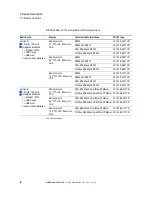
Содержание XV-152 Series

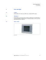
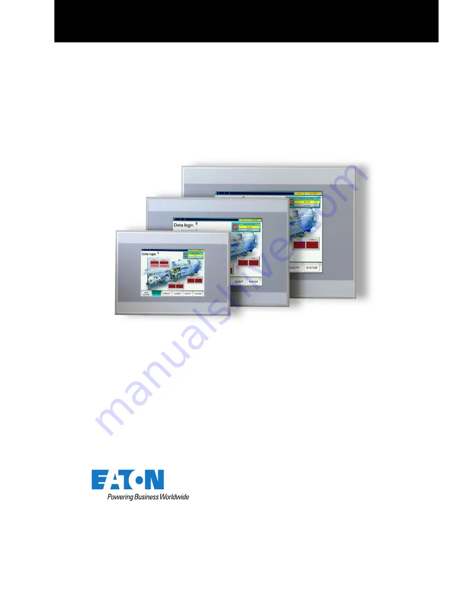
Страница 1: ...Operating Instructions 12 2011 MN04802006Z EN XV 152 MICRO PANEL...

Страница 2: ...G CH 9008 St Gallen All rights reserved also for the translation None of this document may be reproduced or processed duplicated or distributed by electronic systems in any form print photocopy microf...

Страница 3: ...tenance and disposal 13 3 3 5 Prohibited use 13 3 3 6 Requirements for proper operation 14 3 4 Device related hazards 15 4 Operating and indication elements 19 4 1 Operating and indication elements on...

Страница 4: ...ty regulations 53 7 2 Maintenance 54 7 2 1 Cleaning the resistive touch 54 7 2 2 Recalibrating a resistive touch 54 7 2 3 Battery 54 7 3 Service 55 7 3 1 Repairs 55 7 4 Troubleshooting 56 8 Storage tr...

Страница 5: ...storage and disposal The operating system and the application software are not described 1 2 Comments about this document Please send any comments recommendations or suggestions relating to this docu...

Страница 6: ...PANEL establishing communication with the programming PC and creating projects with GALILEO and MXpro 2 MN05010007Z EN System Description Windows CE operation of the Windows CE operating system on MIC...

Страница 7: ...52 can be used as HMI devices or as integrated HMI PLC devices 2 2 Intended use MICRO PANELs XV 152 are primarily used in machine and system building They are designed exclu sively for the visualizati...

Страница 8: ...84TVR CAN RS485 and RS232 XV 152 D6 84TVR Profibus RS485 and RS232 XV 152 D8 84TVR Resistive touch 10 4 TFT LCD 64k colors VGA RS232 XV 152 D0 10TVR RS485 and RS232 XV 152 D4 10TVR CAN RS485 and RS23...

Страница 9: ...mounting the device glued in the device and or loose enclosed 1 Power supply connector for the device 1 Power supply connector for SmartWire DT Master only supplied with XV 152 E devices 1 Stylus Qty...

Страница 10: ...ation Manufacturer address Type designation Power supply required Part no Part No or Art No Serial no Time of manufacturing week year Approval mark and information to the approval Arrangement of inter...

Страница 11: ...rent state of the art and complies with all recognized safety requirements The device must only be installed and commissioned in perfect technical condition and in compliance with this document Read t...

Страница 12: ...NGER Indicates an imminently hazardous situation which if not avoided will result in death or serious injury WARNING Signal word WARNING Indicates a potentially hazardous situation which if not avoide...

Страница 13: ...t must be ensured that any person working with the device in any phase of its lifespan has read and understood the relevant sections of the Operating Instructions 3 3 4 Installation maintenance and di...

Страница 14: ...rating Instructions and must observe the requirements described The ambient conditions stated must be observed See Chapter 9 9 Ambient conditions 69 The maintenance work must be carried out correctly...

Страница 15: ...vice before removing the plug connections WARNING Live parts in the device When the device is opened there is a risk of electric shock if live parts are touched The device must not be opened WARNING P...

Страница 16: ...asons The number of write cycles possible on SD cards is limited A power failure during write operations will most likely lead to loss of data Only remove the SD card when the device is in a de energi...

Страница 17: ...com 17 CAUTION Cleaning the device Damage to the device due to the use of pointed or sharp objects or by liquids Do not use any pointed or sharp objects e g knife for cleaning Do not use any aggressi...

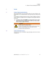
Страница 18: ...3 Safety regulations 3 4 Device related hazards 18 MICRO PANEL XV 152 12 2011 MN04802006Z EN www eaton com...

Страница 19: ...e has the following operating and indication elements on the front Tab 4 Operating and indication elements on the front Fig 2 Operating and indication elements on the front Element Function A Touch se...

Страница 20: ...EN www eaton com 4 2 Operating elements on the service side The device has the following operating elements on the service side Tab 5 Operating elements on the service side Fig 3 Operating elements o...

Страница 21: ...CRO PANEL XV 152 12 2011 MN04802006Z EN www eaton com 21 5 Installation 5 1 Safety regulations Read Chapter 3 Safety regulations 11 before installing and commissioning the de vice This contains import...

Страница 22: ...ice is designed for mounting in control cabinets control panels or control desks It can be mounted horizontally or vertically The following requirements must be fulfilled when selecting a suitable mou...

Страница 23: ...le shield CAUTION Operational malfunctions Use of unsuitable or improperly prepared cables as well as incorrect wiring will mean that neither the values stated in the technical data nor the electromag...

Страница 24: ...ions 7 Fig 4 Interfaces of the device Interface Interface description A USB Host Chapter 5 3 7 31 B Ethernet Chapter 5 3 5 30 C USB Device Chapter 5 3 6 31 D Interfaces depending on the device version...

Страница 25: ...casings with a cable clamp for strain relief The cable clamp must be screwed securely to the connector Connecting the cable shield 1 Strip the cable end so that approx 3 cm of the shield braid is exp...

Страница 26: ...d with D Sub connector A Cable with cable sheath B Heat shrinkable tubing or rubber grommet C Cable clamp D Shield braid E D Sub connector F Mounting screw UNC The EMC values stated in the technical d...

Страница 27: ...ix Contact MSTB 2 5 3 ST 5 08 connector Phoenix order no 1757022 is supplied with the device Tab 7 Assignment of connector The following must be observed when the connector wiring is prepared Tab 8 Pr...

Страница 28: ...tionship of cable length baud rate CAUTION Non isolated interfaces The device may be damaged due to potential differences The GND terminals of all bus stations must be connected Fig 9 RS232 interface...

Страница 29: ...5 3 Interfaces MICRO PANEL XV 152 12 2011 MN04802006Z EN www eaton com 29 When preparing the cables ensure that there is a low resistance connection between the cable shield and the connector casing C...

Страница 30: ...m cable length 100 m Fig 10 Ethernet interface RJ45 socket LED Signal Meaning ACT yellow flashes Ethernet is active data traffic LINK green lit Active network is connected and detected ACT LINK CAUTIO...

Страница 31: ...Device interface supports USB 2 0 Cable Only use shielded USB standard cable Maximum cable length 5 m 5 3 7 USB Host The USB Host interface supports USB 2 0 Cable Only use shielded USB standard cable...

Страница 32: ...em system description engineering installation commissioning and diagnostics of a SmartWire DT netwerk MN05006001Z EN Manual SmartWire DT Units surface mounting engineering installation etc of the sin...

Страница 33: ...k is supplied with current C SWD LED Indicates whether the physical structure of the SmartWire DT network matches the target configuration Each time the power supply is switched on the configurations...

Страница 34: ...ly supplied as a control voltage for the contactor coils For other power supply requirements see Chapter 9 5 2 SmartWire DT Master 65 Wiring WAGO connector order no 734 104 is supplied with the device...

Страница 35: ...4 100LF8 24 with the relevant blade terminals SWD4 8MF2 or SWD4 3 5 10 F8 24 2S prefabricated cable Standard Over current and short circuit protection DIN VDE 0641 Part 11 and IEC EN 60898 Miniature c...

Страница 36: ...ter exists project configuration The PLC runtime system is installed on the device Procedure 1 Press the configuration button Config for at least two seconds The SWD LED of the SmartWire DT Master int...

Страница 37: ...tch the tar get configuration A SmartWire DT slave configured as necessary is missing Orange flashing The physical structure of the SmartWire DT network is read and stored as the target configuration...

Страница 38: ...GND terminals of all bus stations must be connected Fig 17 CAN interface 9 pin D Sub male UNC Pin Signal Assignment 1 nc 2 CAN L Bus line dominant low 3 CAN GND CAN Ground 4 nc 5 nc 6 GND Optional CAN...

Страница 39: ...nce per unit length 60 pF m Core cross section max cable length 0 25 mm2 100 m 0 34 mm2 250 m 0 75 mm2 500 m Cable length Max baud rate 25 m 1000 Kbit s 50 m 800 Kbit s 100 m 500 Kbit s 250 m 250 Kbit...

Страница 40: ...5 Installation 5 3 Interfaces 40 MICRO PANEL XV 152 12 2011 MN04802006Z EN www eaton com Fig 18 Bus segment with four bus stations...

Страница 41: ...maged due to potential differences The GND terminals of all bus stations must be connected Fig 19 Profibus interface 9 pin D Sub female UNC Pin Signal Assignment 1 nc 2 nc 3 B EIA RS 485 line B 4 RTSA...

Страница 42: ...ures a defined idle signal on the bus when no bus station is transmitting These bus terminations should be implemented externally in the connector casing according to the Profibus standard they can al...

Страница 43: ...ing potential Tab 23 Pin assignment of the RS485 interface CAUTION Non isolated interfaces The device may be damaged due to potential differences The GND terminals of all bus stations must be connecte...

Страница 44: ...ible surge impedance 108 132 Max cable length 1200 m Possible baud rates 9600 Bit s 19200 Bit s 38400 Bit s 57600 Bit s 115200 Bit s When preparing the cables ensure that there is a low resistance con...

Страница 45: ...ons for the relevant interface must be observed when wiring the device Any generally applicable regulations and standards must be fulfilled CAUTION Device condensation If the device is or was exposed...

Страница 46: ...1 mm 8 4 devices 261 194 mm 1 mm 10 4 devices 329 238 mm 1 mm Material thickness at the mounting cutout 2 5 mm Eight retaining brackets with a threaded pin each are required for mounting in accor danc...

Страница 47: ...ng the threaded pins until the front of the MICRO PANEL is flush with the surface of the control cabinet at the fixing points CAUTION Poor sealing Poor sealing resulting from the twisting of the seali...

Страница 48: ...d in potentially explosive atmospheres Top and bottom of the device One retaining bracket at each of the fixing positions left right and in the center Left and right on the device One retaining bracke...

Страница 49: ...us When wearing gloves ensure that these are clean They must not be covered with abrasive dust or sharp particles CAUTION Device condensation If the device is or was exposed to climatic changes temper...

Страница 50: ...ng booting the device see Chapter 7 4 Troubleshooting 56 3 Complete the following steps after initial commissioning Document MN05010007Z EN System Description Windows CE 3 1 Adjust the system settings...

Страница 51: ...g 30 SD slot A CAUTION Data loss During a write operation the SD card may lose data or may be destroyed if it is re moved or if there is a power failure Only insert the SD card when the device is in a...

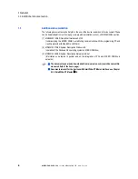
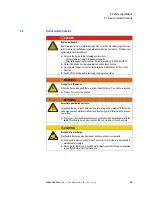
Страница 52: ...6 Operation 6 4 Inserting and removing an SD card 52 MICRO PANEL XV 152 12 2011 MN04802006Z EN www eaton com...

Страница 53: ...tions MICRO PANEL XV 152 12 2011 MN04802006Z EN www eaton com 53 7 Maintenance and service 7 1 Safety regulations Read Chapter 3 Safety regulations 11 before working with the device This contains impo...

Страница 54: ...little cleaning agent onto the damp cloth first 7 2 2 Recalibrating a resistive touch The resistive touch is already calibrated when delivered However it must be recalibrated if it does not respond co...

Страница 55: ...06Z EN www eaton com 55 7 3 Service 7 3 1 Repairs The device must only be opened by the manufacturer or by an authorized repair center Contact your local supplier or Eaton technical support for repair...

Страница 56: ...x torque Chapter 5 4 1 46 Device is faulty Send in your device for repair Display remains or becomes dark Backlight is switched off Check the function in the visualization software Backlight is faulty...

Страница 57: ...pter 9 9 Ambient conditions 69 8 3 Transport Damage to the device must be prevented during transport use an appropriate packaging The ambient conditions must be fulfilled even when the device is trans...

Страница 58: ...27 Materials used in the packaging DANGER Explosive and toxic materials Any improper handling causes a risk of explosion due to the lithium battery soldered in the device Dispose of the device properl...

Страница 59: ...weights 9 1 1 5 7 devices Tab 28 Dimensions and weights of the 5 7 devices Fig 31 Mechanical dimensions of the 5 7 devices in mm Property XV 152 5 7 Height 156 mm Width 212 mm Depth 52 5 mm Thickness...

Страница 60: ...ices Tab 29 Dimensions and weights of the 8 4 devices Fig 32 Mechanical dimensions of the 8 4 devices in mm Property XV 152 8 4 Height 208 mm Width 275 mm Depth 52 5 mm Thickness of front plate 5 mm M...

Страница 61: ...devices Tab 30 Dimensions and weights of the 10 4 devices Fig 33 Mechanical dimensions of the 10 4 devices in mm Property XV 152 10 4 Height 260 mm Width 345 mm Depth 54 mm Thickness of front plate 5...

Страница 62: ...een diagonal 8 4 devices 170 mm 128 mm 8 4 screen diagonal 10 4 devices 211 mm 158 mm 10 4 screen diagonal Color resolution 64k colors Contrast ratio Normally 300 1 Brightness Normally 350 cd m2 Backl...

Страница 63: ...ackup Battery type CR2032 190 mA h maintenance free soldered Backup time in de energized state Normally 10 years Property XV 152 Ethernet 100Base TX 10Base T USB Device USB 2 0 not electrically isolat...

Страница 64: ...od 100 ms Voltage dips 10 ms from rated voltage 24 VDC 5 ms from undervoltage 20 4 VDC Power consumption 5 7 devices Basic device Max 7 W USB stations on USB host Max 2 5 W Total Max 9 5 W 8 4 and 10...

Страница 65: ...0898 Max 3 A1 In accordance with UL 508 and CSA 22 2 No 14 Max 2 A1 Short circuit strength No external protection required e g FAZ Z3 Chapter 5 3 8 3 34 Power loss Normally 1 W Potential isolation No...

Страница 66: ...SmartWire DT interface Tab 37 SWD SmartWire DT interface 1 If SmartWire DT slaves with a total power consumption 0 7 A are connected a power feeder module EU5C SWD PF2 has to be used Repetition rate 1...

Страница 67: ...onductive dust Property XV 152 Front IP65 Enclosure Type 4X indoor use only Required number of retaining brackets and threaded pins for mounting 8 pieces each Rear IP20 Enclosure Type 1 Property XV 15...

Страница 68: ...for residential commercial and light industrial environments Explosion protection in relation to CE ATEX 94 9 EC Zone 22 Category 3D II 3D Ex tc IIIC T70 C IP6x IEC EN 60079 0 Explosive atmospheres e...

Страница 69: ...ditions Property XV 152 Temperature Operation 0 50 C Storage Transport 20 60 C Relative air humidity 10 95 non condensing Vibration in accordance with IEC EN 60068 2 6 Displacement 5 9 Hz 3 5 mm 9 60...

Страница 70: ...9 Technical data 9 9 Ambient conditions 70 MICRO PANEL XV 152 12 2011 MN04802006Z EN www eaton com...

Отзывы: