Eaton TRSM0605, Service Manual
The Eaton TRSM0605 Service Manual is a comprehensive user guide designed to assist you in understanding and maintaining your device efficiently. With easy-to-follow instructions, this manual provides valuable insights, troubleshooting tips, and step-by-step procedures. Download it for free from manualshive.com and enhance your product expertise today.
Share
Download


Reviews:
No comments
Related manuals for TRSM0605

JWM40
Brand: Jensen Pages: 2

Traxshot
Brand: Comica Pages: 28

DA-237
Brand: Takstar Pages: 2

Page station 5
Brand: AMC Pages: 8

BOC-2100
Brand: Steren Pages: 12

CS-X8
Brand: Teac Pages: 24

RCD820
Brand: Curtis Pages: 11

1209YAMMDWMTS
Brand: JVC Pages: 41

0209RYMMDWDAT
Brand: JVC Pages: 10

0603MWMMDWORIJVC
Brand: JVC Pages: 26
0108NYMCREBET
Brand: JVC Pages: 2

0209YAMMDWCDT
Brand: JVC Pages: 2

0310YAMMDWDAT
Brand: JVC Pages: 2
0410YOMMDWCDT
Brand: JVC Pages: 2
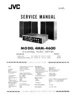
4MM-4600
Brand: JVC Pages: 17

0510KMMCREBET
Brand: JVC Pages: 2

20981IEN
Brand: JVC Pages: 27

0207WMKMDCJEM
Brand: JVC Pages: 48


