January 2006
Page 1 of 14
01-50604-01
Replacing the PanelMate Power Pro 1785 Series, PanelMate ePro
7585x-8 and 7685x-8 Series Backlight Assembly
Introduction
The Backlight Replacement Kit provides a replacement backlight for the PanelMate Power Pro 1785
Series, the PanelMate ePro 7585x-8 Series, and the PanelMate ePro 7685x-8 PS Series (all models)
units. Although the figures provided are for touchscreen models, disassembly for keypad models is
similar. For bulb replacement in keypad units, follow the same procedures as for touchscreen units.
Contents
•
Backlight
•
Disposable Grounding Wrist Strap
Caution
: Electrostatic Discharge (ESD) can damage static-sensitive electronic components. You
should perform these procedures only at an ESD workstation. If an ESD workstation is not
available, you can provide some protection by wearing an anti-static wrist strap and
attaching it to a metal part of the system chassis.
Warning
:
This procedure requires electrical and mechanical skill and should be attempted
only by qualified technicians.
Required Tools
•
Phillips screwdriver—size P0 and P1. Magnetic would be helpful.
•
Nut Driver or socket size ¼”
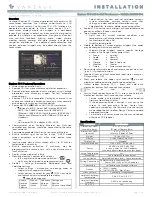
Instructions for Replacing the Backlight in a 1785 Series unit
1. Disconnect the power source cable and any other cables from the PanelMate unit. If a high speed
interface module is attached, remove the module.
2. Remove the cover from the electronics module by unscrewing the screws holding the cover on.
3. Remove the circuit board by removing the standoffs, and the screws holding the circuit board to the
display plate assembly.
4. Disconnect the backlight cable from the inverter. If necessary, you may have to remove the inverter
by removing the screws connecting the inverter to the display plate.
Note
: In newer models, a standoff had been placed next to the backlight cable connector to prevent
it from disconnecting from the inverter. The inverter has to be removed in order to disconnect
the backlight cable.
5. Remove the standoffs on the display plate to release it from the front panel.
6. Remove the display module from the display plate by unscrewing the screws at the corners, and
pulling the backlight cable through the cutout in the display plate.
7. Remove the video cable from the display module.