


779 Washington St., Buffalo, N.Y. 14203-1396 U.S.A. • (716)856-2200 • Fax (716)856-1140 or (716)856-2068
Manufacturers of Eastman Cloth Cutting and Cloth Spreading Machines
Website: www.EastmanCuts.com
Form E-551
Technical Support:
1-800-872-5595
WARNING
This machine is equipped with a very sharp
knife. Keep hands, arms, and hair away from
the knife area at all times.
Misuse of this machine or failure to follow all
safety instructions on this machine and in the
instruction manual may result in serious
personal injuries.
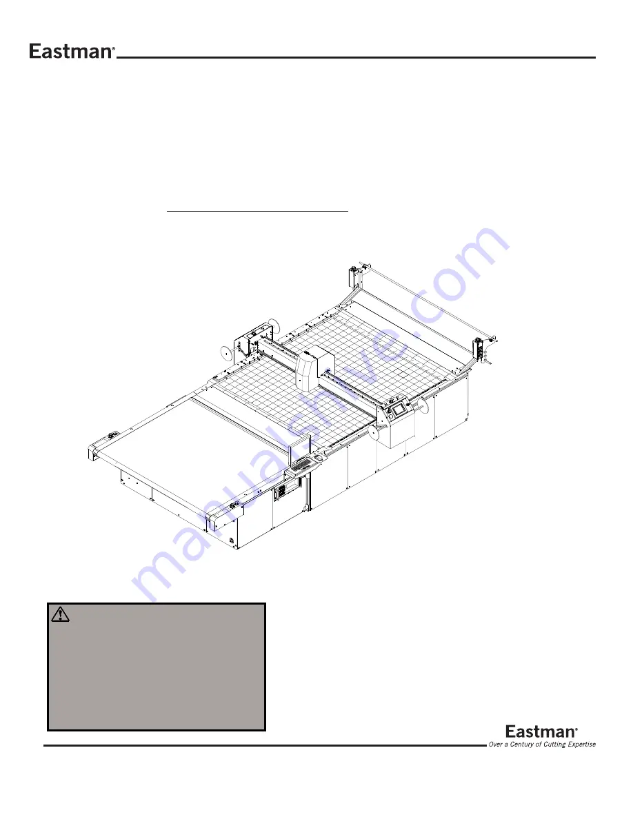
THE EASTMAN
®
Multi-Ply
Automatic Cutting System
Model: MPC 5000
Service Manual


