EAE ROSA, Product Manual
The Nordica ROSA Instructions For Installation, Use And Maintenance Manual is a comprehensive guide designed to assist users with the proper installation, use, and maintenance of the Nordica ROSA product. This manual is available for free download from manualshive.com, providing users with easy access to essential information for maximizing the product's performance and longevity.
Share
Download


Reviews:
No comments
Related manuals for ROSA
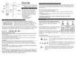
9306
Brand: Taylor Pages: 6

devireg 316
Brand: DEVI Pages: 8

PT59X
Brand: Thermona Pages: 8

TID-A
Brand: jbc Pages: 8

OCD6-1999
Brand: OJ Electronics Pages: 22

WS 2000
Brand: ADE Pages: 48

TSTAT0713K
Brand: Kenmore Pages: 28

05225
Brand: SATA Pages: 60

RFRP
Brand: EPH Controls Pages: 3

CDT2-24
Brand: EPH Controls Pages: 2

CDT2
Brand: EPH Pages: 3

TH232-AF-230
Brand: Aube Technologies Pages: 4

TH140-28
Brand: Aube Technologies Pages: 4

TH108-A-347S3
Brand: Aube Technologies Pages: 2

TH115 A/F/AF
Brand: Aube Technologies Pages: 76

RediFork Pro ET-63
Brand: Maverick Pages: 1

RediChek ET-7
Brand: Maverick Pages: 1

ET-83
Brand: Maverick Pages: 2


