Document:
Date
Created By:
ECO#
LPN00321X0001A1_A
2016-8-22
TMT
006368
INSTALLATION INSTRUCTIONS
E-MS Series
www.e-conolight.com | 888.243.9445 | FAX: 262.504.5409
CAUTIONS
IMPORTANT SAFEGUARDS
When using electrical equipment, basic safety
precautions should always be followed including the
following:
READ AND FOLLOW ALL
SAFETY INSTRUCTIONS
1. DANGER- Risk of shock- Disconnect power before
installation.
DANGER
– Risque de choc – Couper l’alimentation
avant l’installation.
2. This luminaire must be installed in accordance with the
NEC or your local electrical code. If you are not familiar
with these codes and requirements, consult a qualified
electrician.
Ce produit doit être installé conformément à NEC ou votre
code électrique local. Si vous n’êtes pas familier avec ces
codes et ces exigences, veuillez contacter un électricien
qualifié.
3. Suitable for Wet Locations.
Adspte pour les Endroits Mouiles.
4. Wall mount and covered ceiling mount only.
Installation murale et sur plafond couvert seulement.
SAVE THESE INSTRUCTIONS
FOR FUTURE REFERENCE
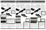
1.
Loosen and remove (2) screw nuts from fixture canopy. Remove
the mounting plate from the fixture. See
Figure 1.
2. Route supply leads through the center of the mounting plate.
Attach mounting plate to the junction box using supplied screws.
See
Figure 2:
3. Make the following wire connections using supplied wire nuts:
a.
Connect supply ground to fixture ground (green).
b.
Connect supply common to fixture neutral (white) lead.
c.
Connect supply 120VAC black to fixture black (line) lead.
d.
Push all leads into the junction box.
4.
Position the fixture and mounting canopy with silicon pad over the
studs on the mounting plate. See
Figure 3.
NOTE: For wet locations, caulk between rear mounting gasket
and mounting surface to prevent water from entering fixture from
behind. A high grade caulking material such as silicone rubber
should be used.
5. Reattach screw nuts that were removed in Step 1. See
Figure 3:
FIXTURE INSTALLATION
Mounting plate
Fixture
Wire nut
Screws for secure
the mounting plate
Screw Nut
FIGURE 1
Notes:
1.
Fixture is intended to operate at 120 VAC only.
2.
Fixture is intended to be mounted over 3" or 4" octagon recessed
junction box, supplied by customer.
3. There should be no items shielding the detection window which
could result in an inability of the sensor to detect motion.
4. There should be no continuously moving objects in front of the
detection window which could result in false triggering.
5.
Avoid installing fixture near air conditioning or heating equipment
to prevent frequent unintended cycling.
Mounting plate
Screws for secure
the mounting plate
FIGURE 2
Fixture
Mounting
Plate
Screw Nut
FIGURE 3