Dykos Systems G4 HD-E series, User Manual
The Dykos Systems G4 HD-E series is a cutting-edge product that combines high-definition video capabilities with advanced features. To make the most of this powerful device, download the comprehensive User Manual for free from our website, ensuring that you have all the necessary information to unlock its full potential.
Share
Download


Reviews:
No comments
Related manuals for G4 HD-E series

Smart Box Series
Brand: Dahua Pages: 361

CDVR-0404R
Brand: CAST Information Co., Ltd. Pages: 59

D862 Series
Brand: Lorex Pages: 84

L154-81
Brand: Lorex Pages: 36

NR8-32M78
Brand: Ganz Pages: 29

CDR 810
Brand: Cobra Pages: 2
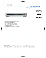
DHG-HDD250 - 30-Hour High-Definition Digital Video Recorder
Brand: Sony Pages: 2

Handycam HDR-CX610E
Brand: Sony Pages: 76

DHG-HDD250 - 30-Hour High-Definition Digital Video Recorder
Brand: Sony Pages: 112

Digital 8 DCR-TRV130E
Brand: Sony Pages: 140

OR-7004DV
Brand: Orion Technology Pages: 104

RK Series
Brand: DSE Pages: 25

DK-CS4-DVR
Brand: DSE Pages: 2

DX Series
Brand: DSE Pages: 55

RK Series
Brand: DSE Pages: 63

SF3038 E2 HD
Brand: Octagon Pages: 2

DVR-3024M
Brand: Appro Pages: 67

DVR-3016, DVR-3016D
Brand: Appro Pages: 81


