

CB-620x_QIG_12Mar_2015
Quasar Gen II CB-6204/CB-6208 Bullet IP Camera Quick Installation Guide
Initial Configuration
1.
Prepare the camera:
Remove the camera from the package.
2.
Attach an Ethernet cable:
a.
Connect one end of a Cat 5 Ethernet cable to the camera’s Ethernet port, and the other end (RJ45) to a Power Sourcing
Equipment (PSE) device, such as a PoE switch.
b.
Verify that the LED on the port is green, indicating a good network connection. A yellow LED flashes when there is network
activity.
NOTE:
The camera IP Address and the subnet mask IP Address are automatically supplied by the DHCP server.
TIP:
A camera setup adapter, such as Veracity Pinpoint, can be used to connect a laptop directly to the camera using PoE.
3.
Set the camera’s IP address:
a.
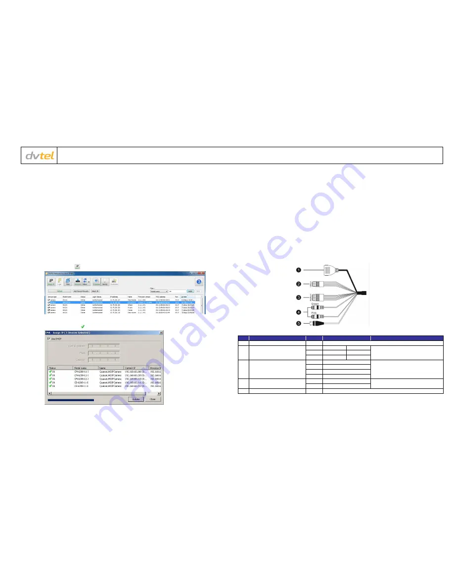
Open the DNA application (version 2.0.4.8 or later). Select the unit requiring IP assignment. See figures below.
b.
To open the DNA
Assign IP
screen, do one of the following:
Select the unit, right-click the mouse, and select the
Assign IP
option
Select the
Assign IP
button from the toolbar
c.
If your network does not have a DHCP server, enter the IP Address, Mask (Netmask) and Gateway values in the dialog box
displayed below.
d.
Click
Update
and wait for
OK
status to be displayed. The IP address has been assigned.
4.
Disconnect the cable:
a.
Disconnect the Ethernet cable. The camera is ready for mounting.
Site Installation
1.
Operating temperature range:
Install the camera where the operating temperature range is between -40°C ~ 50°C (-40° ~ 122°F), 0-95% relative humidity (non-
condensing).
2.
Mount the camera:
Install the Quasar Gen II bullet camera according to the camera’s User and Installation Guide.
3.
Attach cables:
Using the attached cables:
a.
Plug the Cat 5 cable into the camera Ethernet port and plug the other end of the cable into a network switch or an IEEE
802.3af PoE device.
b.
If applicable, connect the Alarm In, Alarm Out, Audio In and Audio Out terminals to external devices. See the figures and
table below.
c.
If applicable connect an external power source to the terminals. See the figure and table below.
Camera Connectors
No
Cable
Pin
Definition
Remarks
1
RJ45
-
For network and PoE connections
2
Power (12VDC/24VAC)
(3-pin Terminal Block)
1
DC 12V −
AC 24V 1
Power connection
2
Reserved
GND
3
DC 12V +
AC 24V 2
3
Alarm I/O
(4-pin Terminal Block)
1
Alarm In −
Alarm connection
2
Alarm In +
3
Alarm Out −
4
Alarm Out +
4
Audio I/O
Green
Audio Out
Two-way audio transmission
Pink
Audio In / Mic In
5
BNC
-
For analog video output


