background image

88

4

Servi

ce


Instructions

Summary of Contents for 884-xxx-M series

Page 1: ...884 Service Instructions ...

Page 2: ...d Property of Dürkopp Adler AG and copyrighted Reproduction or publication of the content in any manner even in extracts without prior written permission of Dürkopp Adler AG is prohibited Copyright Dürkopp Adler AG 2014 ...

Page 3: ...r all subclasses of the machine and contains also the instructions for setting optional accessories of the machine if this is necessary owing to their complexity Provided the machine supplied does not contain some elements then the respective chapters may be ignored The succession of the setting operations is expressed here by sequencing the paragraphs of this booklet When setting check up if the ...

Page 4: ...ersons with appropriate training 7 For service or repair work on pneumatic systems disconnect the machine from the compressed air supply system max 7 10 bar Before disconnecting reduce the pressure of the maintenance unit Exceptions to this are only adjustments and functions checks made by appropriately trained technicians 8 Work on the electrical equipment must be carried out only by electricians...

Page 5: ... 13 2 7 Checking the switch over of the feed clutch 14 2 8 Wheel feed 15 3 Top feed 3 1 Position of the needle holder with single needle sewing machines 17 3 2 Needle feed 18 3 3 Roller foot 20 3 4 Roller foot lifting 21 3 5 Variator of the roller foot drive 22 4 Adjusting the needle bar and the hook 4 1 Hook height 23 4 2 Needle bar height play of needle to hook tip loop stroke 24 4 3 Hook tip gu...

Page 6: ...Index Page 7 Electronic control and sewing machine drive positioning motor 35 7 1 Terminals to PCB connections electromagnetic variant 36 7 2 Terminals to PCB connections pneumatic variant 37 ...

Page 7: ...rder Please observe that various setting positions are dependent on each other Thus it is essential that the settings be conducted while keeping to the order described For all adjustments of parts involved in the stitch formation a new undamaged needle must be inserted This text does not specifically mention any machine covers or panels which must be removed or re mounted in order to conduct inspe...

Page 8: ...e needle bar is at top dead centre the pointer 3 should be aligned with 0 degrees 1 2 1 Sewing machines with minimotor Loosen the handwheel screws with a 3 mm Allen key 1 Position the needle bar in the upper dead centre position Use the retention pin 3 mm diameter to peg the position 2 Turn the handwheel so that the pointer 3 points to 0 degrees on the rotary scale Tighten the first screw with the...

Page 9: ...ing pin 2 which is a part of the sewing machine accessories and which is fixed on the oil tray bottom side into the crank head Loosen two setting screws of the hand wheel flange 4 with the Allen key 3 mm 1 Turn the hand wheel flange with the hollow 6 against the sign 3 Tighten both setting screws with the key 1 and fix the hand wheel on again 7 EN 2 4 1 3 6 5 ...

Page 10: ...crew 3 as far as needed to the right using a 10 mm open ended wrench Verify that the stitch regulator gear is without motion by pressing down on the bartacking lever This fulfils rule 1 Set the scaling ring 4 with stitch length 0 to align with the circular mark 5 Limit the stitch length according to rule 2 For this screw the retention pin 6 into the proper hole The holes are marked with numbers wh...

Page 11: ... and turn the grooved 3 eccentric tappet 2 according to the illustration Fasten with screw 1 Loosen screw 4 on the clamping lever Turn the settings frame 5 so that the shackles 6 are parallel Tighten screw 4 This then fulfils rule 1 The next step is to match up the forwards and reverse stitch lengths Sew ten stitches forwards Press the bartacking lever and then sew ten stitches backwards Rotate th...

Page 12: ...osition Tighten the screw 1 Unscrew the screw on the feed clutch 6 and insert the needle 5 into the hole left after it Turn the clutch 6 with hand until the needle 5 fits 5 mm inwards This fulfils the rule Tighten the four screws 2 Remove the needle 5 and screw the screw back again Caution Risk of injury Turn the main switch off Only carry out this adjustment when the machine is turned off ATTENTI...

Page 13: ...n the position shown in the illustration Now make the fine scale adjustment to the eccentric tappet Continue until you have found the position where the feed lever 1 no longer moves when the bartacking lever is pressed down Tighten screws at eccentric tappet 3 Fasten the weight 4 in the opposite position to the eccentric 3 Caution Risk of injury Turn the main switch off Only carry out this eccentr...

Page 14: ... 5 until you feel it strike the tightening increases in jumps Push the clutch 6 to the right until the end stop is reached Tighten the screws 4 Verify the adjustment Turn the eccentric tappet with your hand in the other direction The resistance during the rotation of the eccentric tappet should increase significantly when the two dashes are lined up Caution Risk of injury Turn the main switch off ...

Page 15: ... Loosen screws 3 Turn the handwheel to position 313 Turn the eccentric tappet in the direction of arrow so that dash 1 is lined up with dash 2 Turn back the eccentric tappet about 2 and move axially on the shaft until the middle is between the limit settings Align the two dashes 1 and 2 again Tighten the screws 3 Caution Risk of injury Turn the main switch off Only carry out this adjustment when t...

Page 16: ...ional direction B of the belt pulley 1 corresponds to the direction specified in the table Do the same for 281 degrees If the rotational directions do not correspond to those specified in the table correct the necessary settings If the clutch switches over too soon on a smaller angle tentatively loosen the adjusting nut 5 see chapter 2 5 and repeat the check Continue loosening until you locate the...

Page 17: ...and hardness Soft or thick materials 0 6 mm Thin materials 0 2 mm 2 The wheel feed knurling should be adapted to the sewn material character Soft material the wheel feed with a crosswise knurling to suppress the prints on the material surface Thick material the wheel feed with larger straight teeth 15 EN A 8 7 6 1 9 2 5 4 ...

Page 18: ...Slide the wheel feed 4 with the pin 5 downwards Replace the wheel feed 4 slide the pin 5 inside and then slide them into the throat plate 1 Fix the pin 5 with the screws 9 Adjust the backlash of the teeth 6 with a setting screw 7 by means of a hexagonal key 2 5 mm 8 Tightening of the screw 7 reduces the backlash and vice versa Turn the hand wheel until the wheel feed turns by a whole revolution Wh...

Page 19: ...thickness Nm 70 110 Remove the thread guide 1 Loosen screw 2 and turn the needle bar with the right groove edge 3 to the needle bar axis in sewing direction and tighten screw 2 Bring the needle bar to the upper dead center and loosen the screw of the needle holder through the bore 4 by using an Allen key of 2 5 mm 5 Turn the needle holder 6 according to the rule and tighten the screw 17 EN 1 2 5 4...

Page 20: ...ly twice as wider than the clearance B 3 The feed movement of the needle should be set so that with maximum stitch lengths the needle leaves the throat plate close to the backward edge of the stitch hole Loosen screw 1 and set the needle bar to the measure C 31mm as shown in the diagram This procedure accomplishes rule 1 Set the adjustment rings 2 and tighten the screws 1 18 1 2 c B A ...

Page 21: ...2 is accomplished Set the maximum stitch length as described in chapter 2 Set the needle to the position in which it leaves the throat plate insert Dismantle the rear cover and loosen screw 6 Set the needle manually to the position shown in fig 1 and tighten screw 6 19 EN 3 5 4 6 Fig 1 ...

Page 22: ...foot ends with the left hand edge of the stitch hole 8 Loosen screw 1 Displace the presser foot bar vertically according to rule 1 Insert the Philips screw driver 2 that is part of the accessories into the hole of the roller foot holder 3 and turn the presser foot bar 4 together with the roller foot holder 3 until the Philips screw driver comes to a right angle with the longitudinal axis of the ma...

Page 23: ...e depicted position and simultaneously screw in screw 3 until it butts against the lever 4 The lever 2 remains in the depicted position Put a spacer of 5 6 mm underneath the roller foot and push the lever 5 manually according to the figure above until it stops Tighten screw 1 This procedure accomplishes rule 1 Remove screw 3 and mount the electromagnet of the presser foot lifting 6 In order to che...

Page 24: ...er B 34 mm by turning the setting nut 3 Make sure that there is no material displacement between upper and lower feed Sew two narrow strips of sewing material of about 30 cm together If the strips after sewing are vaulted upward or downward this indicates a difference between upper and lower feed The position of the setting nut 3 must be adjusted accordingly After reaching the point of zero differ...

Page 25: ...t Rule The distance A should be 1 0 up to 1 1 mm Loosen screws 1 and set the height A according to the rule Tighten the screws 1 Caution Danger of injury Turn the main switch off Proceed with the hook setting only with the sewing machine switched off 23 EN 1 A ...

Page 26: ...troke position 2 3 mm by using the locking pin 1 5 mm degree 205 Loosen four screws 2 and turn the hook tip 3 to the needle axis Loosen screw 4 position the needle bar and needle to the distance measure A and tighten screw 4 Loosen the two screws 5 and screws 6 and displace the hook column 7 from off the needle to the distance measure B Tighten screws 5 and 6 Check whether the hook tip 3 is positi...

Page 27: ...t the setting screw of the guard plate 1 by using an Allen key of 3 mm 3 so that the needle does not touch the hook tip 2 Checking Exert a light pressure on the needle see arrow and turn the hook at the same time The setting is not incorrect if the guard plate 1 slightly deflects the needle Caution Danger of injury Turn the main switch off Proceed with the setting of the hook guard and loop former...

Page 28: ...re A with max release should be 0 5 mm Set the degree 310 on the scale of the handwheel Loosen screw 2 by the screwdriver 3 set the bobbin housing release 1 so that the distance measure A according to rule 2 is accomplished Tighten screw 2 26 1 1 2 3 A ...

Page 29: ...rding to the rule Check whether the oil lubrication is sufficient Place a sheet of paper near the hook run the machine to full speed and observe whether a trace of sprinkling oil appears on the paper If you want to choke the lubrication screw the screw 1 deeper and vice versa Caution Danger of injury Turn the main switch off Proceed with the setting of the hook lubrication only with the sewing mac...

Page 30: ...ng to rule 1 to end at figure 2 tighten screw 2 Loosen screw 3 Turn the stop sleeve 4 in the direction of the arrow until the check spring 5 comes off the body 6 Turn the stop sleeve 4 against the direction of the arrow until the check spring 5 touches the body 6 Turn both parts 4 and 6 together to reach the distance measure A Detain the body 6 and turn the stop sleeve 4 for another 30 against the...

Page 31: ...ley to the top using the screws 1 Push the toothed belt to the right so that both screws 1 are accessible Loosen screws 1 and set the distance measure A according to rule 1 tighten screws 1 Determine the bobbin filling by adjusting screw 2 Screw in screw 2 for 1 to 2 mm but a bobbin on the bobbin winder shaft and wind on thread Check the filling level as soon as the bobbin winder turns off If nece...

Page 32: ...he counter knife 3 The thread pulling knife must not develop any pressure on the counter knife 3 The cutting pressure between the knives 1 and 3 will develop during thethread pulling knife 1 slight turning to the cutting position due to the elevated position of its cutting edge surface Fix thethread pullinge 5 with the screw 2 Caution Danger of injury Turn the main switch off Proceed with the thre...

Page 33: ...e recess 6 Loosen the screw 5 with the hexagonal key 3 mm With your hand slightly turn the thread pulling knife 1 to the starting position and lock it with the needle shank 2 Turn the lever 3 in the arrow direction to the stop and then fix it with the screw 5 Remove the needle 2 and mount the throat plate insert back again Caution Danger of injury Turn the main switch off Proceed with the thread c...

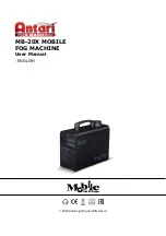
Page 34: ...32 4 3 5 ...

Page 35: ...ghtly turn the hand wheel to the angle 100 Insert the locking pin 1 according to the picture and lean it against the shaft 2 Insert the feeler gauge 0 1 mm between the cam 3 and the roller 4 Slide the cam 3 to the left fully to the stop until the clearances inside the mechanism are set Fix the cam 3 with one locking screw with the key 5 Remove the pin 1 and tighten also the other locking screw of ...

Page 36: ...ng can easily slip out turn the hand wheel to the angle 290 tilt the hook cover up and slightly bend the spring 1 downwards with a screwdriver Repeat the seam sewing do the thread cutting perform a test of the tension needed to pull the thread out and slightly bend the spring until the thread is reliably retained with the spring Caution Risk of injury Turn the main switch off Only adjust the clamp...

Page 37: ... electronic components Turn off the main switch Remove the plug from the socket Electrostatic discharges can cause damage to PCBs and other components You can obtain a certain protection by wearing anti static gloves or wrist wraps that you can connect for grounding on the mass of any unpainted metal piece of the machine head or on the switch cabinet Handle the PCBs with utmost caution They are ve...

Page 38: ...onnecting cable 9870 688002 for connector on base plate thread trimmer solenoids sewn material edge horizontal trimmer X17 microswitch of sewn material edge trimmer vertical oblique X18 sewn material edge trimmer motor F1 sewn material edge trimmer resettable fuse R1 Autoselect resistor sewing machine class selection S11 tilt sensor J1 switch if the sewing machine has a direct drive DAC control si...

Page 39: ...3000 needle switch off 10 0V FW STL FA auxiliary outlet thread wiper zero stitch length at thread trimming X20 external outlet controlled with auxiliary pushbutton on keypad Imax 50mA X21 connection of auxiliary cable for bottom distribution FA 24V GND X22 external blocking of operation e g thread lever guard switch etc X23 connection of a side DAC switchboard direct drive X24 material edge trimme...

Page 40: ...mer Str 190 33719 Bielefeld Germany Phone 49 0 521 925 00 E Mail service duerkopp adler com www duerkopp adler com Subject to design changes Printed in Germany Dürkopp Adler AG Service Instructions 0791 884651 EN 00 0 07 2014 ...

Reviews: