background image

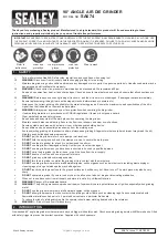
4-1/2” ANGLE GRINDER

Model 03150

ASSEMBLY AND OPERATING INSTRUCTIONS

3491 Mission Oaks Blvd., Camarillo, CA 93011

Visit our Web site at: http://www.harborfreight.com

Copyright


 2003 by Harbor Freight Tools

®

.  All rights reserved.  No portion of this

manual or any artwork contained herein may be reproduced in any shape or form

without the express written consent of Harbor Freight Tools.

For technical questions, please call 1-800-444-3353.

®

Summary of Contents for 3150

Page 1: ...isit ourWeb site at http www harborfreight com Copyright 2003 by Harbor Freight Tools All rights reserved No portion of this manual or any artwork contained herein may be reproduced in any shape or form without the express written consent of Harbor Freight Tools For technical questions please call 1 800 444 3353 ...

Page 2: ...ow all instructions listed below may result in electric shock fire and or serious injury SAVE THESE INSTRUCTIONS WORK AREA 1 Keep your work area clean and well lit Cluttered benches and dark areas invite accidents 2 Do not operate power tools in explosive atmospheres such as in the presence of flammable liquids gases or dust Power tools create sparks which may ignite the dust or fumes SKU 03150 PA...

Page 3: ...ized outlet Do not change the plug in any way Double insulation eliminates the need for the three wire grounded power cord and grounded power supply system 6 Avoid body contact with grounded surfaces such as pipes radiators ranges and refrigerators There is an increased risk of electric shock if your body is grounded 7 Do not expose power tools to rain or wet conditions Water entering a power tool...

Page 4: ...ARE 16 Use clamps not included or other practical ways to secure and support the workpiece to a stable platform Holding the work by hand or against your body is unstable and may lead to loss of control 17 Do not force the tool Use the correct tool for your application The correct tool will do the job better and safer at the rate for which it is designed 18 Do not use the power tool if the Power Sw...

Page 5: ...ng or its own cord Contact with a live wire will make exposed metal parts of the tool live and shock the operator 3 Maintain labels and nameplates on the Polisher Waxer These carry important information If unreadable or missing contact Harbor FreightTools for a replacement 4 Always wear safety impact eye goggles and heavy work gloves when using this tool Using personal safety devices reduce the ri...

Page 6: ...into an electrical outlet Turn off the tool and unplug it from its electrical outlet beforeleaving 14 Always unplug this tool from its electrical outlet before performing inspec tion maintenance or cleaning procedures 15 WARNING Some dust created by power sanding sawing grinding drilling and other construction activities contain chemicals known to the State of Cali fornia to cause cancer birth def...

Page 7: ...wire cord and three prong grounding plug The plug must be connected to a properly grounded outlet If the tool should electrically malfunction or break down grounding provides a low resistance path to carry electricity away from the user reducing the risk of elec tric shock See Figure A 2 The grounding prong in the plug is connected through the green wire inside the cord to the grounding system in ...

Page 8: ...an use either a two or three wire extension cord 2 As the distance from the supply outlet increases you must use a heavier gauge extension cord Using extension cords with inadequately sized wire causes a serious drop in voltage resulting in loss of power and possible tool damage See Figure C next page 3 The smaller the gauge number of the wire the greater the capacity of the cord For example a 14 ...

Page 9: ...d damp or wet areas SKU 03150 PAGE 9 RECOMMENDED MINIMUM WIRE GAUGE FOR EXTENSION CORDS 120 VOLT NAMEPLATE AMPERES At Full Load EXTENSION CORD LENGTH 25 Feet 50 Feet 75 Feet 100 Feet 150 Feet 0 2 0 18 18 18 18 16 2 1 3 4 18 18 18 16 14 3 5 5 0 18 18 16 14 12 5 1 7 0 18 16 14 12 12 7 1 12 0 18 14 12 10 12 1 16 0 14 12 10 16 1 20 0 12 10 Based on limiting the line voltage drop to five volts at 150 o...

Page 10: ...ll a 4 1 2 diameter Grinding Wheel not included depress the Stop Pin part 11 to keep the Spindle part 27 from turning Insert the Wrench part 58 into the two holes located in the Flange Nut part 32 Unscrew and remove the Flange Nut Then release pressure on the Stop Pin See Figure D 3 Insert the 4 1 2 diameter Grinding Wheel fully onto the Spindle part 27 making sure the Grinding Wheel fits snugly a...

Page 11: ...cleaned by rubbing them with a pencil eraser If the Carbon Brushes are excessively worn they must both be replaced at the same time To clean or replace the Carbon Brushes unscrew and remove the Brush Caps part 42 to expose the Carbon Brushes Pull out both Carbon Brushes from their Brush Holders part 40 and insert two new Carbon Brushes in the Brush Holders Then replace the Brush Caps See Figure D ...

Page 12: ...BY THE BUYER THE BUYER ASSUMES ALL RISK AND LIABILITY ARISING OUT OF HIS OR HER REPAIRS TO THE ORIGINAL PRODUCT OR REPLACEMENT PARTS THERETO OR ARISING OUT OF HIS OR HER INSTALLATION OF REPLACEMENT PARTSTHERETO Part Description Part Description 1 Spring 30 Flange 2 Spring Washer 31 Grinding Wheel 3 Washer 32 Flange Nut 4 Nut 33 Screw 5 Pinion Gear 34 Screw 6 Bearing 35 Stator 7 Bearing Cap 36 Cabi...

Page 13: ...purposes only and are not available individually as replacement parts ASSEMBLY DIAGRAM 11 12 13 14 2 3 1 15 16 17 18 19 20 21 22 23 24 2 3 25 2 3 26 27 28 29 30 31 32 50 51 2 52 45 43 53 44 46 47 48 49 57 39 38 55 42 41 40 54 54 37 36 35 2 33 10 9 34 8 7 6 5 4 58 REV 04 06 ...

Reviews: