The heterodyne conversion system, in
conjunction with the use of a SAW filter,
insures optimum vestigial selectivity for
adjacent channel headends.
The modulators are designed to accept any
standard audio/video source such as NTSC
video and audio baseband signals from a
satellite receiver, TV camera, videotape
recorder, TV demodulator, or similar signal
source.
The modulators accept standard (sync
negative) polarity video at a 0.7 to 2.5 Vp-p
level. All level controls are located on the front
panel for ease of operation. Output level of
+45 dBmV is typical and is adjustable from
+30 to +45 dBmV.
Field-defeatable audio pre-emphasis enables
passing of BTSC encoded standard baseband
stereo audio signals. The Drake model
MMTS20 stereo encoder may be used with the
VMM when stereo audio is required.
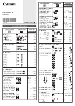
The R.L. Drake VMM 600/VMM 860 Video
Modulator System is a professional quality
modular headend system designed to optimize
rack space. Up to 12 VMM 600 and/or
VMM 860 modulators can be racked alongside
a single power supply in the Drake 12 position
rack mount or up to 4 modulators can be racked
in the 4 position rack mount. Either model is a
high quality, fixed channel heterodyne audio/
video modulator.
The VMM 600 provides a modulated visual and
RF carrier output on any single VHF channel
2-13; Lowband channel A8; Midband channel
A-I and A5-A1; Superband channel J-W;
Hyperband channel AA-ZZ and AAA-XXX
(CATV 63-86) or UHF channel 14-35.
Aeronautical channels are offset positive with
a tolerance of ±5 kHz as required by FCC rules.
The VMM 860 provides a modulated visual and
RF carrier output on any single Hyperband
channel 87-135 or UHF channel 36-69.
12 POSITION RACK MOUNT POWER SUPPLY
®
VMM 600/VMM 860 VIDEO MODULATOR SYSTEM
® is a registered trademark of the R.L. Drake Company
© Copyright 2005 R.L. Drake Company P/N: 3852631C-04-2005
4 POSITION
RACK MOUNT
POWER SUPPLY
OR
VMM 600/VMM 860 MODULAR
SINGLE-CHANNEL MODULATORS
F1
F2
F3
F4
F5
F6
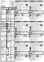
R1 - VIDEO INPUT Connector
This is the baseband video input to the IF
circuits. This input accepts baseband input
thru 4.2 MHz video at levels from 0.7 Vp-p to
1.5 Vp-p.
R2 - AUDIO INPUT Connector
This is an unbalanced audio input to the IF
circuits. This “RCA” (phono) connector input
accepts baseband thru 15 kHz audio at a
nominal level of 250 mV RMS (approximately
0 dBm). NOTE: An externally accessible test
point jumper defeats the audio pre-emphasis
for stereo capability.
R3 - DC INPUT Connector
This 3-pin connector (Male) accepts the
appropriate mating DC power cable. Observe
proper orientation and wiring.
R4 - RF OUTPUT Connector
This is the modulator output.
INTERNAL JUMPER
FRONT PANEL DESCRIPTION REAR PANEL DESCRIPTION
Figure 1 Figure 2
R1
R2
R3
R4
AUDIO PRE-EMPHASIS
(On) MONO
AUDIO PRE-EMPHASIS
(Off) STEREO w/MMTS20
F1 - AUDIO Level Control
The setting of this screwdriver adjustment
determines the peak aural carrier deviation.
Clockwise rotation increases the carrier
deviation.
F2 - VIDEO Level Control
The setting of this screwdriver adjustment
determines the video modulation level.
Clockwise rotation increases the modulation
depth.
F3 - POWER Indicator
Lights when the unit is connected to the
required source of DC power via the rear panel
DC INPUT connector.
F4 - A/V Ratio Control
This screwdriver adjustment varies the level of
the aural carrier over a range from 12 to 19 dB
below the visual carrier. The aural carrier
should be adjusted to approximately 15 dB
below the visual carrier (normal operation).
Clockwise rotation increases the aural carrier
level and thus decreases the A/V ratio.
F5 - "CH#" (Channel)
The modulator is factory aligned to the
channel number indicated.
F6 - RF Output Level
This screwdriver adjustment permits
decreasing the RF output level approximately
12 dB below its specified output level as the
control is rotated counterclockwise. The
maximum output level is set with the
adjustment fully clockwise.
+5V
+12V
GND
R
Order From:
800-423-2594
www.multicominc.com
[email protected]