All health and safety procedures and recommendations must be followed as detailed in the Horizon Quantum User Manual.
This product is to be installed and maintained by experienced telecommunications personnel only. Installations must adhere to specifications listed in the Horizon Quantum User Manual.
Horizon Quantum is to be installed with proper grounding, surge arrestors and -48 VDC power in accordance with instructions contained in the Horizon Quantum User Manual.
Customer Support International Help Desk:
+1 613 271 7010
email:
web:
http://support.dragonwaveinc.com
DragonWave Inc.
http://www.dragonwaveinc.com
83-000071-01-01-02
Page
1
of
2
Quick Reference Guide
v1.2
Horizon Quantum
Rel. 1.01.00
Rel. 1.00.00
Mechanical
Modem (IDU)
4.3 cm x 32 cm x 22 cm; 2.4 kg
1.7 in x 12.75 in x 8.6 in; 5.3 lbs.
Radio (without antenna)
20 cm x 20 cm x 9 cm; 3.2 kg
7.8 in x 7.8 in x 3.6 in; 7 lbs.
Antenna Wind Loading
110 kph (70 mph) Operational
200 kph (125 mph) Survival
Antenna Mount Adjustment +/- 45° Az; +/- 22° El
Radio Operating Temperature
Quantum
Standard Power + Solar Shield
-40°C to + 60°C (-40°F to +140° F)
DUO
High Power + Standard Power
-40°C to + 45°C (-40°F to +113° F)
Standard Power + Solar Shield
-40°C to + 60°C (-40°F to +140° F)
IDU Operating Temperature
0°C to + 50°C ( 0°F to +122° F)
ODU Humidity
100 % Condensing
IDU Humidity
95% Non-Condensing
Altitude
4500 m (14,760 ft)
NEB-3 Compliant
Yes
Power
Power Input Required
-36 VDC to -60 VDC
Optional Adapter Available
100-240VAC / 47-63 Hz to -48VDC
Power Consumption:
Single Channel, Single Radio
< 105 Watts
Dual Channel, Single Radio
< 126 Watts
Dual Channel, Dual Radio
< 172 Watts
Features
Capacity w/Accelerator
Variable from 10 to 2000 Mbps full duplex CIR
2.5x capacity up to 4 Gbps with DPRM
Base Capacity
Variable from 10 to 800 Mbps full duplex CIR
2x capacity up to 1.6 Gbps with DPRM
Interface
6X1000/100/10 BaseT + 2 SFP Ports
Latency GigE
< 200μs, Typical 120μs GigE
Packet Size
64 to 9600 Bytes
Flow Control
Yes
Prioritization
8 levels served by 4 queues, based on 802.1p/q,
MPLS, DSCP ToS Bits
Modulation Shifting
Yes, Hitless
Loopback
Yes, IF , Radio, Network
XPIC
Yes, enables Co-Channel Cross Polarization
Synchronization
SynchE ready
Mounting Structures
Minimum 2 3/8” OD thick-wall (Sched. 80):
galvanized mast for 30 and 60 cm antennas
Minimum 3” OD thick-wall (Sched. 80)
galvanized mast for 90 and120 cm antennas
Minimum 4” OD thick-wall (Sched. 80)
galvanized mast for 180 cm and larger antennas
Twist and Sway
Maximum allowed twist of structure or mount
should be ½ of the antenna beamwidth. Generally
< 1° degree for 30 and 60 cm antennas, and <½°
degree for 120 cm and larger antennas. Maximum
allowed sway should be no more than 1/10th of
beam size at target.
Cables and Installation
IF cables from Horizon Qauntum modem to radio are 50 Ohm coaxial. Times Microwave LMR-
400/600/900 (and equivalents) can be ordered from DWI or vendors in 30, 60 and 90 meter lengths.
Grounding cables for radio chassis and DWI supplied surge arrestors: 6 AWG stranded bare copper.
Maximum Allowable Cable Loss
Quantum IDU Configuration
Transmit Cable Loss
Budget (dB)
Receive Cable Loss
Budget (dB)
Single Modem with Combiner
14
23
Dual Modem with Combiner
14
20
Dual Modem no combiner
18
24
Transmit IF Frequency (Tx IF) = 400-700 MHz Receive IF Frequency (Rx IF) = 1600-1900 MHz
DragonWave has determined that the DWI supplied patch cables (one 6‟ and one 15‟) plus two surge
arrestors add approximately 1.1 dB of extra loss @ 700 MHz, and 2.0 dB of extra loss @ 2000 MHz
Cable Type
(Times Microwave)
Outer
Diameter
Single Modem,
Single IF
(23dB)
Dual Modem,
Single IF (20dB)
(with combiner)
Dual Modem,
Dual IF (24dB)
(no combiner)
LMR-400
3/8”
351‟
301‟
367‟
LMR-600
9/16”
539‟
462‟
564‟
LMR-900
7/8”
797‟
683‟
835‟
Available Configurations
Single modem/Single radio
Dual modem/Dual Radio
Dual modem/Single radio
Modem redundancy
Note:
2 radio licenses are required for 2 channels or 2 radio configurations.
Adjacent channel configurations are supported.
System Capacity
Horizon Quantum throughput can reach 1.6 Gbps (over the air bandwidth), depending upon hardware
and configuration:
1.
One IF connector: (includes IF combiner)
a.
400 Mbps using 1 radio channel
b.
800 Mbps using 2 radio channels
2.
Two IF connectors (no IF combiner)
a.
400 Mbps using 1 radio channel and 1 radio
b.
800 Mbps using 1 radio channel on each of 2 radios (2 channels total)
3.
Two radio channels on each of two Horizon Quantum units results in1600 Mbps, when
using aggregation protocols or technology.
Note:
Horizon Quantum has a compression ratio of up 2.5:1 across a link. Therefore, with
compressible data, Horizon Quantum throughput can reach 4 Gbps, depending upon
hardware and system configuration.
System Configuration
Logging In
– Serial Port, Telnet, Web Interface
Default IP address:192.168.10.100
Default subnet is: 255.255.0.0
Super User Default Username:
energetic
, default password:
wireless
Serial port speed: 19200 baud, 8 data bits , no stop bits, 1 parity, no flow control (19200 N81)
Default management is via Ethernet Port 3 (out of band)
Configure your pc with an IP address in the same subnet.
Command Line Interface (CLI) Overview: Serial Port or Telnet to system IP address
CLI uses GET and SET commands or config wizards with interactive question/answer.
Full context sensitive help is available for all CLI commands. Type „
?
‟ followed by a partial
command.
For example „
? statistics
‟ will provide all commands with the word „
statistics
’
.
Pressing the TAB key after entering a partial command will complete the command if unique.
Up and down (
↑ and ↓) arrow keys will recall previous CLI entries.
Unrecognized CLI commands will receive a NAK response.
Issue „
save mib
‟ command to save the new settings to flash memory. Some changes require
the system to be reset to implement the new settings. („
reset system
‟ CLI command)
Web Interface (GUI)
(must be enabled)
Enter the target system‟s IP address into web browser (Example:
http://192.168.10.100
)
Configuration Steps
Radio Band & System Mode is applied to both modems simultaneously with a single command.
Each modem supports its own frequency/channel and Tx Power
(dual radio only)
1.
Configure the system capacity
(Web: Basic Configuration page)
-
get system capacity
-
set system capacity <index>
(setting single/dual modem or radio, or redundancy)
Note:
For system capacities with
„Dual Wireless Ports; a license key is required.
To check if the unit is shipped with the license key, „
get licensed feature groups’
.
See Index 5.
If the
unit is not licensed for „Dual Wireless Ports‟:
Please contact
or +1 (613) 271-7010.
2.
Configure the Radio Band.
(Web: Basic and Port Configuration page)
-
set radio band <radio band>
Example: set radio band fcc11_a_30
(11GHz B1 30MHz Channels
– DUO/AP Radio)
Example: set radio band fcc23_2_50_R5
(23GHz B2 50MHz Channels
– Quantum Radio)
3.
Configure the System Mode. (Web: Basic Configuration page)
-
set system mode <system mode>
(used for setting speed and modulation)
Example: set system mode hz30_212_256qam
(212 Mbps at 256QAM modulation)
4.
Configure the frequency bank. (Web: Basic Configuration page)
-
set frequency bank <txhigh/txlow>
5.
Review available frequency pairs and indexes. (Web: Basic Configuration page)
-
get frequency bank
6.
Program transmit and receive frequency by index. (Web: Basic Configuration page)
-
set programmed frequency <index>
-set programmed frequency <index> wireless_port2
(for dual modem)
7.
Configure the IP address, subnet mask and default gateway. (Web: Basic Configuration page)
Note:
Selecting yes after either of these commands will apply the settings immediately.
-set ip address <xxx.xxx.xxx.xxx>
-set subnet mask <xxx.xxx.xxx.xxx>
-set default gateway <xxx.xxx.xxx.xxx>
Note:
The user can select any user ports (P1 to P8) and data paths (DP1 to DP4) to manage the
system.
8.
Configure the network management interface. (Web: Basic Configuration page)
set network management interface
(interactive wizard)
By default the management interface is p3.
Note:
By assigning the management ports as the ports belonging to an IPG the management traffic
can be isolated from other user traffic. (Out Of Band Management)
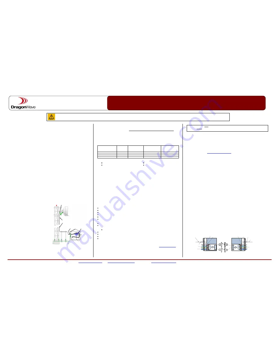
9.
Configure Isolated Port Groups.
IPGs are used to interconnect multiple isolated networks by creating multiple switching domains.
-set ipg config <group name><enable|disable><port list>
Example:
In Band:
-set ipg config ipg5 enable p3,dp1
(enable ipg5 to correspond with port3 and dp1)
Out of Band:
-set ipg config ipg5 enable p3
(enable ipg5 to correspond with port3)
ipg = isolated port group (1-5) dp = data path (1-4).
P1
P2
P3
P4
P5
P6
P7
P8
DP1
DP2
DP3
DP4
P1
P2
P3
P4
P5
P6
P7
P8
DP1
DP2
DP3
DP4
C
la
ss
ifi
e
r
Q
o
S
M
o
d
e
m
C
la
ss
ifi
e
r
Q
o
S
M
o
d
e
m
IPG2
IPG4
IPG3
IPG1
IPG3
IPG4
IPG2
IPG1
Management port
Management port
IPG5
IPG5
Factory Default Configuration
Note:
It is suggested both link ends are configured the same.
To default IPGs back to default each IPG must be reprogrammed.
NOTE:
Switch ports must be properly configured in order to pass VLAN tagged traffic.
By default all ports are considered access Ports and will only allow untagged or VLAN ID 1.
(see configuration Step 10, below)
Radio
Coaxial
IF Cable
Ethernet
Switch
(if
req’d)
Rack
-
48 V DC
Horizon
Quantum
Surge
Arrestor
Surge
Arrestor