Dräger X-am 1700, Technical Manual
The Dräger X-am 1700 is a reliable gas detection device used by professionals to ensure safety in hazardous environments. Stay informed with the Technical Manual, available for free download from our website. This comprehensive manual will guide you on proper usage and maintenance of this essential tool.
Share
Download


Reviews:
No comments
Related manuals for X-am 1700

Compliance Kiosk
Brand: WatchGas Pages: 10

Viper
Brand: Trident Pages: 6

Defuser EX
Brand: K40 Pages: 2

65-2437RK-05
Brand: RKI Instruments Pages: 19

MV9
Brand: XENOX Pages: 5

Goldmaster TR Speacial
Brand: White's Pages: 12

Sensepoint XCL
Brand: Honeywell Pages: 6
GasAlertMicro 5 Series
Brand: Honeywell Pages: 2
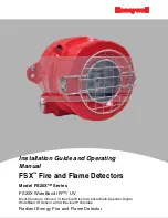
FS20X Series
Brand: Honeywell Pages: 33

S-C02/T
Brand: Aereco Pages: 8

F-Guard-IR3-H2-HD
Brand: GasTech Pages: 46

TOTAL BAND PROTECTION XTR-690
Brand: Whistler Pages: 9

Pro-58
Brand: Whistler Pages: 8

PRO-68XRi
Brand: Whistler Pages: 18

GT-438Xi
Brand: Whistler Pages: 36

PRO-78GXi
Brand: Whistler Pages: 43

GT-438G
Brand: Whistler Pages: 41

2011112/716/12
Brand: Pilot Communications Pages: 15


