Dormakaba HSW EASY SAFE, Installation Instructions Manual
The Dormakaba HSW EASY SAFE is a cutting-edge sliding door system that ensures enhanced security and convenience. To ensure seamless installation, we provide a comprehensive Installation Instructions Manual that can be easily downloaded for free from our website. Unleash the full potential of this exceptional product by referring to our user-friendly manual available at manualshive.com.
Share
Download


Reviews:
No comments
Related manuals for HSW EASY SAFE

2400 Series
Brand: Gainsborough Pages: 3
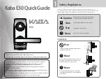
E30
Brand: Kaba Pages: 4

PL727
Brand: QiLocks Pages: 3

BKS B 1956
Brand: GU Pages: 60

20 FUNCTION
Brand: Longleaf Collection Pages: 2

SGL
Brand: Eco Pages: 2

e-Elite 5000-RF
Brand: TownSteel Pages: 12

Stock Locks C1804
Brand: COMPX Pages: 1

Stock Locks C1801
Brand: COMPX Pages: 1

Stock Locks C1775
Brand: COMPX Pages: 1

BE468 series
Brand: Schlage Pages: 36

CyberLock FlashLock
Brand: eka Pages: 4

95527
Brand: Drill Master Pages: 5

Kevo
Brand: Weiser Pages: 2

iPass IP100W
Brand: IDTECK Pages: 32

Timberline CB-241
Brand: COMPX Pages: 1

OR-ZS-851
Brand: Orno Pages: 11

WE 5001/2 BIS
Brand: Extel Pages: 10


