


This manual contains
important safety information
and must be made available to
personnel who operate and
maintain this machine.
46674960_en_C_02/18
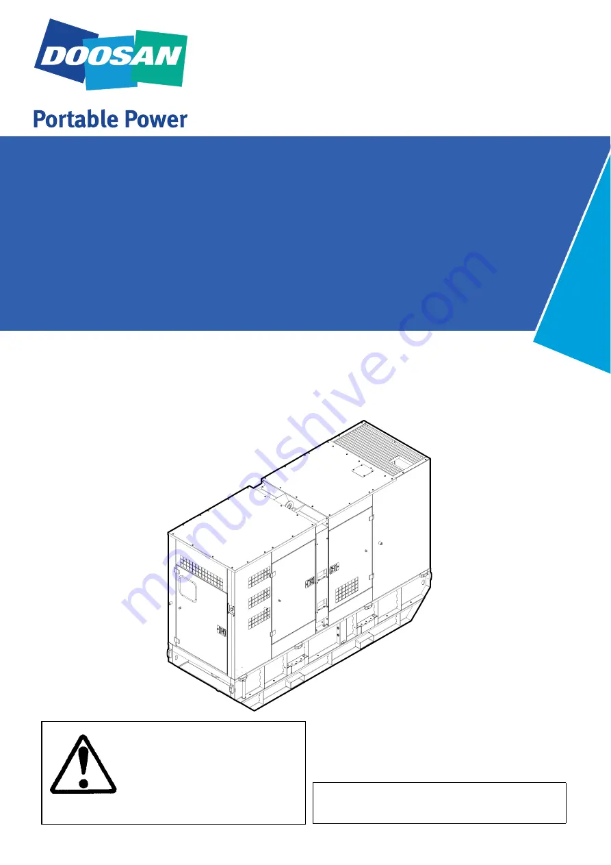
G20, 30, 40 SIIIA
OPERATION & MAINTENANCE MANUAL
Original Instruction
G20 SIIIA
SERIAL No : G02030001 ->
G30 SIIIA
SERIAL No : G03030001 ->
G40 SIIIA
SERIAL No : G04030001 ->
Summary of Contents for G20 SIIIA
Page 2: ......
Page 4: ...4 G20 30 40 SIIIA Operation Maintenance Manual ...
Page 10: ...10 G20 30 40 SIIIA Operation Maintenance Manual ...
Page 15: ...15 G20 30 40 SIIIA Operation Maintenance Manual WARNING Flammable liquid ...
Page 20: ...20 G20 30 40 SIIIA Operation Maintenance Manual ...
Page 121: ......


