


COPYRIGHT © 2013-2017 Dometic Corporation. All Rights Reserved.
No part of this publication may be reproduced, translated, stored in a retrieval system, or transmitted in any form or by any means
electronic, mechanical, photocopying, recording or otherwise without prior written consent by Dometic Corporation. Every precaution
has been taken in the preparation of this manual to ensure its accuracy. However, Dometic Corporation assumes no responsibility for
errors and omission. Neither is any liability assumed for damages resulting from the use of this product and information contained
herein.
RETAIN THESE INSTRUCTIONS FOR
FUTURE REFERENCE
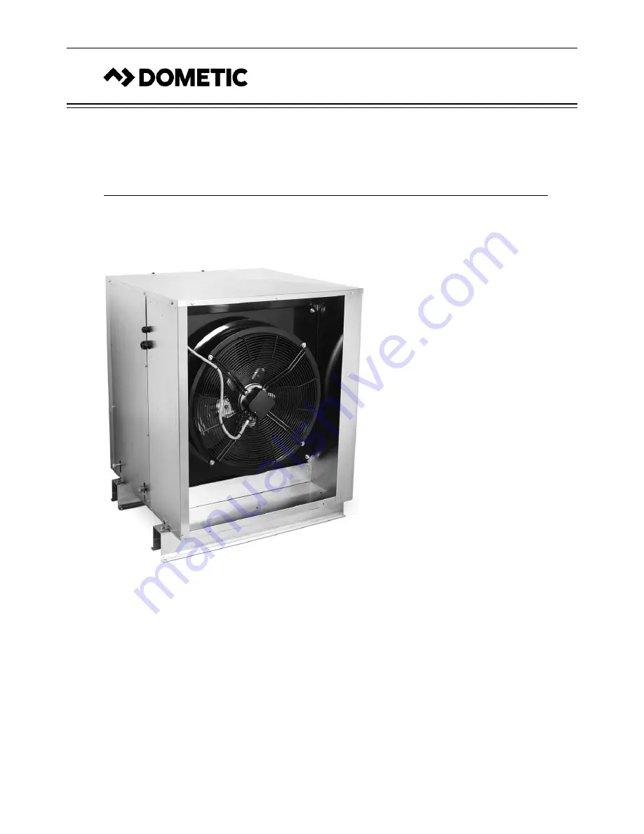
DuraSea Condenser Unit
Installation, Start-Up & Service Manual
DuraSea Condenser Unit
Dometic Corporation
Rev. 20170601
PN 337982
L-3153
Summary of Contents for DuraSea DCA120D
Page 27: ...NOTES ...


