HT25 - SERVICE
1
SERIAL NUMBER RECORD
HT25 - SERVICE
1
SERIAL NUMBER RECORD
SERVICE
SERIAL NUMBER RECORD
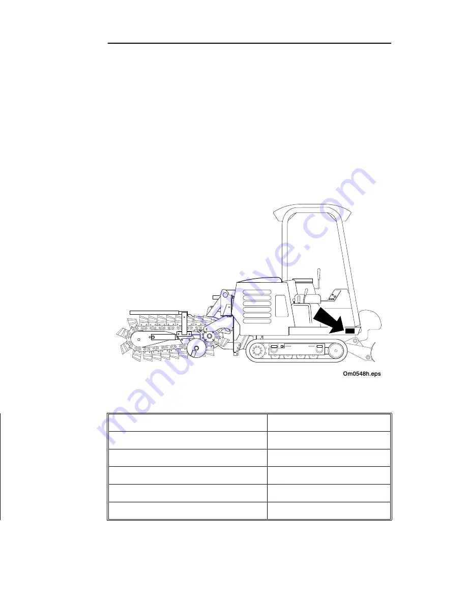
Record serial number and date of purchase in spaces provided.
Tractor serial number is located as shown.
Date of Manufacture:
Date of Purchase:
Tractor Serial Number:
Front Attachment Serial Number:
Engine Serial Number:
Trailer Serial Number:
SERVICE
SERIAL NUMBER RECORD
Record serial number and date of purchase in spaces provided.
Tractor serial number is located as shown.
Date of Manufacture:
Date of Purchase:
Tractor Serial Number:
Front Attachment Serial Number:
Engine Serial Number:
Trailer Serial Number:
Summary of Contents for ht25
Page 8: ...8 HT25 CONTENTS ...
Page 10: ...10 HT25 OVERVIEW ...
Page 34: ...34 HT25 SAFETY SAFETY ALERTS ...
Page 52: ...52 HT25 TRENCHING ...
Page 58: ...58 HT25 BACKHOE ...
Page 72: ...72 HT25 LUBRICATION ...
Page 92: ...92 HT25 MAINTENANCE ...
Page 101: ......
Page 102: ......
Page 103: ...HT25 103 ...