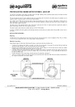
background image

100 ESP

Installation Guide

© 1999 Directed Electronics, Inc. Vista, CA N410 10-99

®

®

Summary of Contents for 100 ESP

Page 1: ...100 ESP Installation Guide 1999 Directed Electronics Inc Vista CA N410 10 99 ...

Page 2: ...nection Guide 6 Plug In LED and Valet Program Switch 11 Harness 2 H2 Door Lock Outputs 12 Door Lock Wiring Diagrams 12 Type A Door Locks 12 Type B Door Locks 13 Type C Door Locks 14 Type D Door Locks 15 Type E Door Locks 16 Type F Door Locks 16 Transmitter Receiver Learn Routine 17 To advance from one channel to another 18 To exit learn routine 18 Transmitter Configurations 18 Standard Configurati...

Page 3: ...ontrol module see diagram Two 471T remote transmitters The plug in status LED The plug in Valet Program switch Primary Harness H1 Blue Valet Program switch plug Plug in LED port H2 Door Lock Harness Port 3 pin Data Program Plug Pre wired Failsafe Starter Kill Relay ...

Page 4: ...any airbag systems will display a diagnostic code through their warning light after they lose power Disconnecting the battery requires this code to be erased a procedure that can require a trip to the dealer Before beginning the installation Check with the customer on status LED location Remove the domelight fuse This prevents accidentally draining the battery Roll down a window to avoid being loc...

Page 5: ...TPUT RED CONSTANT POWER INPUT BROWN HORN HONK OUTPUT YELLOW SWITCHED IGNITION INPUT BLACK CHASSIS GROUND INPUT VIOLET NO FUNCTION BLUE 200 mA SECOND UNLOCK OUTPUT GREEN NO FUNCTION BLACK WHITE 200 mA DOMELIGHT SUPERVISION OUTPUT WHITE BLUE 200 mA CHANNEL 3 VALIDITY OUTPUT WHITE PARKING LIGHT OUTPUT ORANGE 500 mA GROUND WHEN ARMED OUTPUT H1 1 H1 2 H1 3 H1 4 H1 5 H1 6 H1 7 H1 8 H1 9 H1 10 H1 11 H1 1...

Page 6: ... Never interrupt any wire other than the starter wire This wire provides a 200mA output to flash the parking lights This is suitable for driving light control wires in Toyota Lexus BMW some Mitsubishi some Mazda etc If the vehicle has a positive parking light circuit a relay must be used to flash the parking lights This wire provides a 200 mA output whenever the transmitter code controlling Channe...

Page 7: ...irectly to the domelight circuit as the output cannot support the current draw of one or more light bulbs The H1 6 BLUE output is used for progressive unlock A progressive unlock system unlocks the driver s door when the unlock disarm button is pressed and unlocks the passenger doors if the unlock disarm button is pressed again within 15 seconds after unlocking the driver s door The BLUE wire outp...

Page 8: ...8 1999 Directed Electronics Inc Vista CA Type A polarity system Wire relays as shown Type B polarity system Connect the BLUE H1 6 wire to the unlock wire in the vehicle and wire the relay as shown ...

Page 9: ...em Wire relays as shown Connect this wire to bare metal preferably with a factory bolt rather than your own screw screws tend to either strip or loosen with time We recommend grounding all your components to the same point in the vehicle H1 8 BLACK chassis ground connection ...

Page 10: ...n It outputs a single pulse when locking the doors with the remote and two pulses when unlocking with the remote This wire will also output pulses for 30 seconds when the Panic Mode is activated If the vehicle has a horn circuit an outboard relay can be used to interface with the system as shown below Before connecting this wire remove the supplied fuse Connect to the positive battery terminal or ...

Page 11: ...lay or a low current input The transis torized output can only supply 200 mA of current Connecting directly to a solenoid motor or other high current device will cause it to fail plug in LED and valet program switch The LED and the Valet Program switch both plug into the control module The status LED plugs into the small two pin port while the Valet Program switch should be plugged into the larger...

Page 12: ...ive pulse system the module will be damaged Here is a test Cut the wire which pulses 12V on lock and then operate the switch to unlock If all doors unlock the vehicle uses a Type A system If you lose all door lock operation in both directions you are operating the master switch in a Type C system If one or more but not all motors stop operating you have cut a wire leading directly to one or more m...

Page 13: ...stems some other Fords also use Type B The switch will have three wires on it and one wire will test ground all the time One wire will pulse when the switch locks the doors and the other wire will pulse when the switch unlocks the doors This type of system is difficult to mistake for any other type IMPORTANT Remember that the functions of these wires reverse between Type A and Type B type B pulses...

Page 14: ...one direction only you have located one of the target wires The switch that lost all operation is the master switch If one switch works both direc tions and the other switch works only one direction you have a Type A system If both switches still operate but one or more doors have stopped responding entirely you have cut a motor lead Reconnect it and continue to test for another wire Once both wir...

Page 15: ...ck actuator inside the door Other vehicles may only require one actuator installed in the driver s door if all door locks are operated when the driver s lock is used This type of installation is required to operate factory lock systems in Volvo except 850 SAAB and most Mazda Isuzu and Subaru models The fuse used on 12V inputs should be 7 5A per motor installed in the vehicle IMPORTANT Do not conne...

Page 16: ... when doors are locked To interface see diagram below The system must be programmed for 3 5 second door lock pulses see Operating Settings Learn Routine section of this guide Type F door locks usually require a negative pulse to unlock and cutting of the same wire to lock the door In some vehicles these are reversed Type F door locks are found in some late model Nissan Sentras 240SX and 1992 and l...

Page 17: ...ate the selected channel and the horn will honk if connected Do not release the Valet Program switch NOTE Channel Nine of the Transmitter Learn Routine will delete all transmitters that are pro grammed into the system as well as change the operating settings back to the default settings see Operating Settings Learn Routine section of this guide To use this option select Channel 9 LED will blink ni...

Page 18: ...more and hold it The horn will honk three times to confirm it is ready to receive the code from the transmitter to program Channel 3 The learn routine will be exited if The ignition is turned off The Valet Program switch is pressed too many times More than 15 seconds elapses between steps One long horn honk if connected indicates that the Learn Routine has been exited transmitter configurations Th...

Page 19: ...e Learn Routine program Button I into System One as the arm disarm button Do this with all four remotes 2 Do the same with System Two except program Button II of all four remotes as the arm disarm button If using DEI 475T four button remotes all auxiliary channels are available on both vehicles Before program ming make a list of all channels on each vehicle and decide which button s should control...

Page 20: ...horn will also honk five times if connected 3 Transmit The transmitter buttons are used to select the desired feature setting As shipped the unit is configured to the default LED ON settings Pressing the Channel 1 transmitter button usually Button I will program the feature to the LED ON setting The LED will light solid stop flashing to indicate the setting The horn will honk once if con nected Pr...

Page 21: ...ition is turned on The Valet Program switch is pressed too many times More than 15 seconds elapses between steps One long horn honk if connected indicates that the Learn Routine has been exited features menu FEATURE DEFAULT LED ON SETTINGS LED OFF SETTINGS NUMBER PRESS CHANNEL 1 TRANSMITTER BUTTON PRESS CHANNEL 2 TRANSMITTER BUTTON 1 Active arming Passive arming 2 Arm disarm confirmation honks ON ...

Page 22: ...R LOCK PULSE DURATION Some European vehicles such as Mercedes Benz and Audi require longer lock and unlock pulses to operate the vacuum pump Programming the system to provide 3 5 second pulses will accommodate door lock interface in these vehicles The default setting is 0 8 second door lock pulses See Mercedes Benz and Audi 1985 and Newer Type E Door Locks section diagram 8 DOUBLE PULSE UNLOCK OFF...

Page 23: ...following the Transmitter Learn Routine When installing the system it is possible to preset all of the operation settings using the master dealer remote However when the system is operated using the master dealer remote a special set of dealer default settings are fol lowed The dealer default settings are used to ensure that every vehicle equipped with this system is protected at all times Only th...

Page 24: ...s the LED plugged into the small white port on the side of the control unit See Plug In LED and Valet Program Switch section Door locks operate backwards This unit has easily reversed lock unlock outputs Recheck Harness 2 Door Lock Outputs section to see if you have reversed these The horn honks when the unit enters panic mode but the confirmation honks do not work when locking and unlocking Are t...

Reviews: