background image


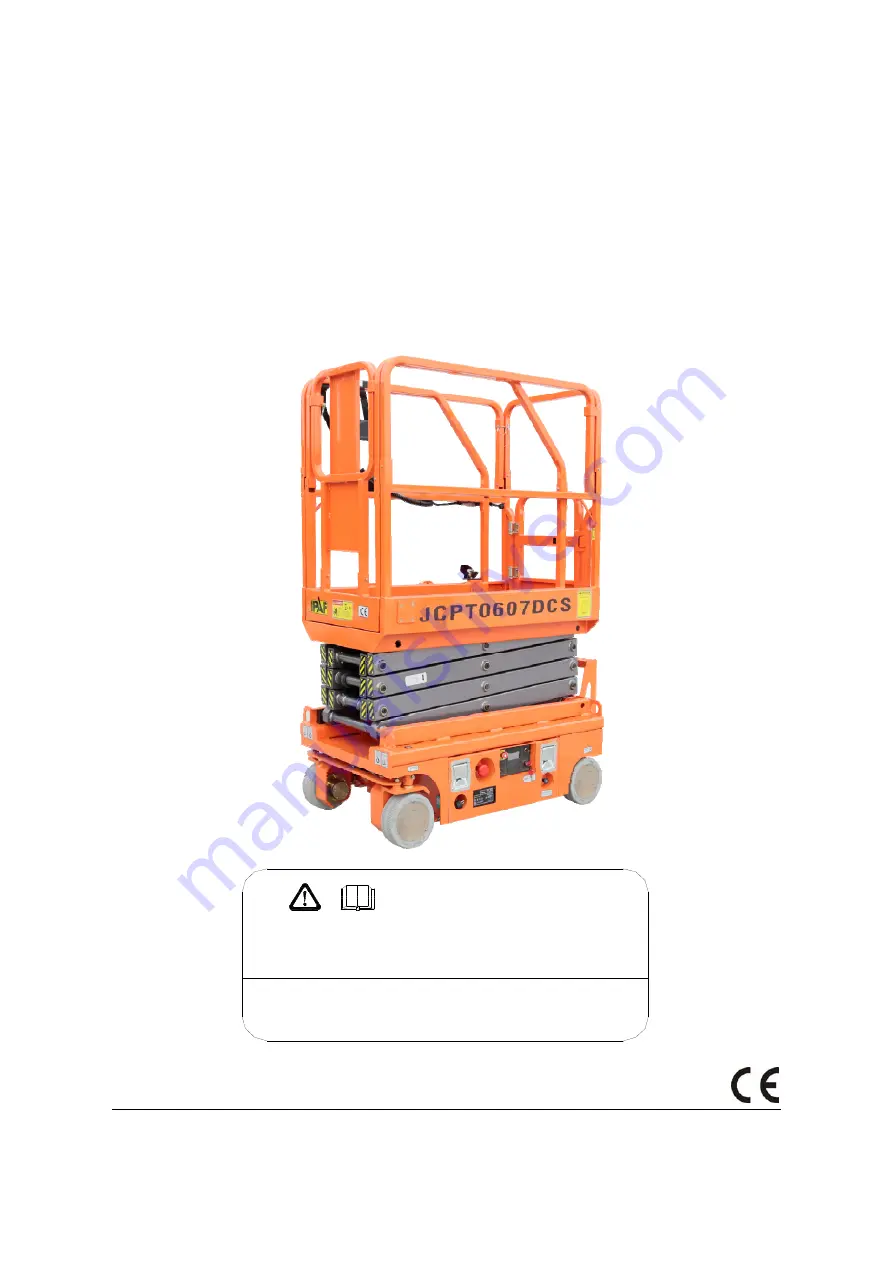
SELF-PROPELLED SCISSOR LIFTS 

OPERATOR’S MANUAL 

with Maintenance Information and Parts List


( For JCPT0607DCS ) 


Part Number: SM0115111


Zhejiang Dingli Machinery Co., Ltd. 

First Edition, November    2015 Printing

WARNING

THE MANUFACTURER SHALL NOT BE HELD LIABLE IN CASE OF FAULTS

OR ACCIDENTS DUE TO NEGLIGENCE, INCAPACITY, INSTALLATION BY
UNQUALIFIED TECHNICIANS AND IMPROPER USE OF THE MACHINE

DO NOT OPERATE THIS MACHINE UNTIL YOU READ AND UNDERSTAND

ALL THE DANGERS,W ARNINGS AND CAUTIONS IN THIS MANUAL

Summary of Contents for JCPT0607DCS

Page 1: ...Machinery Co Ltd First Edition November 2015 Printing WARNING THE MANUFACTURER SHALL NOT BE HELD LIABLE IN CASE OF FAULTS OR ACCIDENTS DUE TO NEGLIGENCE INCAPACITY INSTALLATION BY UNQUALIFIED TECHNICIANS AND IMPROPER USE OF THE MACHINE DO NOT OPERATE THIS MACHINE UNTIL YOU READ AND UNDERSTAND ALL THE DANGERS WARNINGS AND CAUTIONS IN THIS MANUAL ...

Page 2: ...OPERATOR S MANUAL with Maintenance Information Version of the Record i Version of the Record Version Number Create Date SM0115111_Rev1 0 2015 11 ...

Page 3: ......

Page 4: ...7 Owners Users and operators We appreciate your choice of our machine for your application Our number one priority is user safety which is best achieved by our joint efforts We feel that you make a major contribution to safety if you as the equipment users and operators 1 Comply with employer job site and governmental rules 2 Read understand and follow the instructions in this and other manuals su...

Page 5: ......

Page 6: ...u read understand and obey all applicable governmental regulations You are properly trained to safely operate the machine Decal Legend DINGLI product decals use symbols color coding and signal words to identify the following Safety alert symbol used to alert personnel to potential personal injury hazards Obey all safety messages that follow this symbol to avoid possible injury or death Red used to...

Page 7: ... 350kV 6 10m 350kV to 500kV 7 62m 500kV to 750kV 10 67m 750kV to 1000kV 13 72m Allow for platform movement electrical line sway or sag and beware of strong or gusty winds Keep away from the machine if it contacts energized power lines Personnel on the ground or in the platform must not touch or operate the machine until energized power lines are shut off Do not operate the machine during lightning...

Page 8: ... in the stowed position across uneven terrain debris unstable or slippery surfaces and near holes and drop offs Do not drive the machine on or near uneven terrain unstable surfaces or other hazardous conditions with the platform raised Do not push off or pull toward any object outside of the platform Maximum allowable manual force Model Application manual force Maximum occupants JCPT0607DCS Outdoo...

Page 9: ... distances between the operator the machine and fixed objects Maintain a firm grasp on the platform rail when removing the rail pins Do not allow the platform guard rails to fall Operation on Slopes Hazard Do not drive the machine on a slope that exceeds the slope and side slope rating of the machine Slope rating applies to machines in the stowed position Maximum slope rating stowed Maximum side s...

Page 10: ...obstructions Limit travel speed according to the condition of the ground surface congestion slope location of personnel and any other factors which may cause collision Component Damage Hazard Do not use any battery or charger greater than 24V Do not use the machine as a ground for welding Explosion and Fire Hazard Do not operate the machine in hazardous locations or locations where potentially fla...

Page 11: ...cycle Do not contact the battery terminals or the cable clamps with tools that may cause sparks Component Damage Hazard Do not use any battery charger greater than 24V to charge the batteries Electrocution Burn Hazard Connect the battery charger to a grounded AC 3 wire electrical outlet only Inspect daily for damaged cords cables and wires Replace damaged items before operating Avoid electrical sh...

Page 12: ...al 4 Platform entry gate 5 Main Platform 6 Lift Cylinder 7 Entry ladder 8 Drive wheels 9 Emergency lowering knob 10 Ground Control Panel 11 Batteries charger 12 Main power switch 13 Steer Wheels 14 Scissor 15 Safety arms 16 Lanyard anchorage point 17 Platform extension 18 Manual storage container 18 2 1 4 5 6 7 8 12 16 15 13 14 17 3 9 10 11 ...

Page 13: ...2 6 9414069 Label Capacity 240kg 1 7 9414109 Caution Max manual force 400N Indoor 200N Outdoor 2 8 9614065 Cosmetic JCPT0607DCS 2 9 9514103 Cosmetic Mark 1 10 9514201 Cosmetic CE 1 11 9413013 Danger Crushing hazard 1 12 9514301 Cosmetic IPAF 1 13 9313011 Instructions Safety arm 2 14 9311011 Instructions Forklift pockets 4 15 9311027 Instructions Wheel load 450kg 4 16 9311015 Instructions Tie down ...

Page 14: ...OPERATOR S MANUAL with Maintenance Information Decals 9 11 1 2 3 4 5 5 6 7 8 9 10 12 13 13 17 16 14 14 15 18 15 17 16 17 16 20 22 15 17 16 21 4 7 8 15 19 ...

Page 15: ...OPERATOR S MANUAL with Maintenance Information Decals 10 ...

Page 16: ...m Standard Maximum hydraulic pressure functions 155 bar System voltage 24 V Tire size Φ230 80 mm Airborne noise emissions 70 dB Maximum sound level at normal operating workstations A weighted Vibration value does not exceed 2 5m s2 Maximum slope rating Stowed position 25 Maximum side slope rating Stowed position 25 Note Slope rating is subject to ground conditions and adequate traction Maximum wor...

Page 17: ...sition to operate the machine 3 LED 4 Platform up down Switch Move the switch UP and the platform will raise Move the switch DOWN and the platform will lower 5 Key switch for platform off ground control selection Turn the key switch to the platform position and the platform controls will operate Turn the key switch to the off position and the machine will be off Turn the key switch to the ground p...

Page 18: ...l Panel 1 Function enable switch for lift and drive functions 2 Thumb rocker switch for steer functions 3 Proportional control handle 4 Horn button 5 Lift function select button 6 Drive function select button 7 Drive speed button 8 LED 9 Red Emergency Stop button 8 9 1 2 3 4 5 6 7 ...

Page 19: ... hold the function enable switch to enable the drive function on the platform control handle Move the control handle in the direction indicated by the blue left arrow on the control panel and the machine will turn to the lift direction that the blue arrow points Move the control handle in the direction indicated by the yellow right arrow on the control panel and the machine will turn to right dire...

Page 20: ...s designed to discover if anything is apparently wrong with a machine before the operator performs the function tests The pre operation inspection also serves to determine if routine maintenance procedures are required Only routine maintenance items specified in this manual may be performed by the operator Refer to the list on the next page and check each of the items If damage or any unauthorized...

Page 21: ...bles Hydraulic hoses fittings cylinders and manifolds Battery pack and connections Drive motors Wear pads Tires and wheels Ground strap Limit switches alarm beacon and Potentiometer Nuts bolts and other fasteners Platform overload components Platform entry gate Safety arm Platform extension s Scissor pins and retaining fasteners Platform control joystick Brake release components Check entire machi...

Page 22: ... if the workplace is suitable for safe machine operation It should be performed by the operator prior to moving the machine to the workplace It is the operator s responsibility to read and remember the workplace hazards then watch for and avoid them while moving setting up and operating the machine Workplace Inspection Be aware of and avoid the following hazardous situations Drop offs or holes Bum...

Page 23: ... machine as it was intended Fundamentals The function tests are designed to discover any malfunctions before the machine is put into service The operator must follow the step by step instructions to test all machine functions A malfunctioning machine must never be used If malfunctions are discovered the machine must be tagged and removed from service Repairs to the machine may only be made by a qu...

Page 24: ...off or platform position 10 Move up and hold the platform up down switch Result No function should operate 11 Turn the key switch to ground control position 12 Move up and hold the platform up down switch Result The platform should raise 13 Move down and hold the platform up down switch Result The platform should lower then stop at the height is 1 3 m The descent alarm should sound while the platf...

Page 25: ...e control panel Result The steer wheels should turn in the direction that the blue left arrow points on the control panel 31 Depress the thumb rocker switch in the direction identified by the white right arrow on the control panel Result The steer wheels should turn in the direction that the white right arrow points on the control panel Test Drive and Braking 32 Press and hold the function enable ...

Page 26: ...ction indicated by the white down arrow Result The drive function should not work in either direction 43 Lower the platform and drive the machine off the block Test the Pothole Guards Note The pothole guards should automatically deploy when the platform is raised The pothole guards activate another limit switch which allows the machine to continue to function If the pothole guards do not deploy an...

Page 27: ...o reach work areas located above and over machinery or equipment The Operating Instructions section provides instructions for each aspect of machine operation It is the operator s responsibility to follow all the safety rules and instructions in the operator s safety and responsibilities manuals Using the machine for anything other than lifting personnel along with their tools and materials to an ...

Page 28: ... function enable switch on the control handle 3 Move the control handle according to the markings on the control panel To Steer 1 Press the drive function select button 2 Press and hold the function enable switch on the control handle 3 Turn the steer wheels with the thumb rocker switch located on the top of the control handle To Drive 1 Press the drive function select button 2 Press and hold the ...

Page 29: ...3 m 0 3 m 3 6 m 0 083 100 8 3 If the slope exceeds the maximum slope or side slope rating the machine must be winched or transported up or down the slope See Transport and Lifting section Operation from Ground with Controller Maintain safe distances between operator machine and fixed objects Be aware of the direction the machine will travel when using the controller Battery Level Indicator Full Lo...

Page 30: ...eck wire lock pins 10 Fold down the right rail assembly Keep hands clear of pinch points 11 Replace the removed pin back into rear rail bracket 12 Remove the left rear main deck wire lock pins 13 Fold down the left rail assembly Keep hands clear of pinch points 14 Replace the removed pin back into rear rail bracket 15 Fold down the rear rail assemble Keep hands free of pinch points How to Raise th...

Page 31: ...PCU ALARM 53 TM1 ALARM 54 PRESS SENSOR ERROR 57 OVERLOAD 58 POTHOLE 59 HIGH POSTION LIMIT 61 TILTING X 62 TILTING Y 63 ANTI HAND CLAMP 64 LEFT BRAKE ERROR 65 RIGHT BRAKE ERROR 66 BATTERY LOW 69 POWER RELAY SLEEP 90 TM1 PCB HOT 91 TM1 RADIATOR HOT 95 TRACATION TUNING NOT DONE 98 BRAKE RELESAE 99 BYPASS 101 ECU E2PROM ALARM 102 ECU WATCHDOG FAULT 110 CANBUS TIMEOUT 1 PCU CPU0 111 CANBUS TIMEOUT 2 PC...

Page 32: ...CHECK FAULT 128 PIN45 INP10 REDUNDANT CHECK FAULT 129 PIN46 INP11 REDUNDANT CHECK FAULT 130 PIN47 INP12 REDUNDANT CHECK FAULT 131 PIN48 INP13 REDUNDANT CHECK FAULT 132 PIN49 INP14 REDUNDANT CHECK FAULT 133 PIN50 INP15 REDUNDANT CHECK FAULT 134 PIN19 INP RELAY REDUNDANT CHECK FAULT 135 PIN20 INP BRAKE REDUNDANT CHECK FAULT 136 PIN23 INP M1 REDUNDANT CHECK FAULT 137 PIN24 INP M2 REDUNDANT CHECK FAUL...

Page 33: ...LE VALUE GREATER THAN MAX 160 PIN01 OUT00 REDUNDANT CHECK FAULT 161 PIN02 OUT01 REDUNDANT CHECK FAULT 162 PIN04 OUT02 REDUNDANT CHECK FAULT 163 PIN05 OUT03 REDUNDANT CHECK FAULT 164 PIN08 OUT04 REDUNDANT CHECK FAULT 165 PIN09 OUT05 REDUNDANT CHECK FAULT 166 PIN11 OUT06 REDUNDANT CHECK FAULT 167 PIN13 OUT07 REDUNDANT CHECK FAULT 168 PIN17 OUT08 REDUNDANT CHECK FAULT 169 PIN18 OUT09 REDUNDANT CHECK ...

Page 34: ... TM1 ERR OVER TENSION 224 TM1 ERR UNDER TENSION 225 TM1 ERR HIGH TEMP PCB 226 TM1 ERR HIGH TEMP RADIATOR 227 TM1 ERR OUT1 OVER CURRENT 228 TM1 ERR OUT2 OVER CURRENT 229 TM1 ERR OUT3 OVER CURRENT 230 TM1 ERR WDO 231 TM1 ERR WDO PER DATA VALIDITY 232 AL TM PUMP MOTOR OPEN 233 AL TM M1 OPEN 234 AL TM M2 OPEN 235 AL TM M1 WIRING 236 AL TM M2 WIRING 237 AL TM EXITATION OPEN 238 AL TM EXITATION WIRING 3...

Page 35: ...eck communications cable connections and other wiring If that does not resolve the problem try replacing the PCU or ECU 53 System Initialization Fault TM1 may be malfunctioning replace it 54 Pressure Sensor Fault Check the wiring to the sensor and then the sensor itself Also check to make sure that the correct option is properly selected or not for load sensing 55 Angle Sensor Fault Check the wiri...

Page 36: ...ght If so check the coil itself to see if it is open or shorted 65 Right Brake Coil Fault Check the connections to the Coil s terminals and make sure they are tight If so check the coil itself to see if it is open or shorted 66 Charge battery 69 Restart the power 90 TM1 over current 91 TM1 over current 95 Turning the traction motor 99 Bypass was enabled by human 101 115 Please contact manufacturer...

Page 37: ... Install the battery vent caps 4 Charge the battery 5 Check the battery acid level when the charging cycle is complete Replenish with distilled water to the bottom of the fill tube Do not overfill To Charge Battery 1 Be sure the battery is connected before charging 2 Open the battery compartment The compartment should remain open for the entire charging cycle Maintenance free battery 3 Connect the...

Page 38: ... or secured before releasing the brakes Brake Release Operation 1 Chock the wheels to prevent the machine from rolling 2 Pull out the red Emergency Stop button on both the ground and platform controls to the on position 3 Press and hold lift switch to down position in ground control meanwhile turn on the key switch to the Ground position The brake will be released after Alarm alerts 4 If you want ...

Page 39: ...se a minimum of four chains or straps Use chains or straps of ample load capacity Adjust the rigging to prevent damage to the chains Lifting the Machine with a Forklift Be sure the extension deck controls and component trays are secure Remove all loose items on the machine Fully lower the platform The platform must remain lowered during all loading and transport procedures Position the forklift fo...

Page 40: ...s for each type of scheduled inspection Make copies of the Pre delivery Preparation report to use for each inspection Store completed forms as required Maintenance Schedule There are five types of maintenance inspections that must be performed according to a schedule daily quarterly semi annually annually and two year The Scheduled Maintenance Procedures Section and the Maintenance Inspection Repo...

Page 41: ...performed by qualified service technicians according to the manufacturer s specifications and the requirements listed in the responsibilities manual Instructions Use the operator s manual on your machine The Pre delivery Preparation consists of completing the Pre operation Inspection the Maintenance items and the Function Tests Use this form to record the results Place a check in the appropriate b...

Page 42: ...tion to learn how to perform these inspections If any inspection receives an N tag and remove the machine from service repair and re inspect it After repair place a check in the R box Legend Y yes acceptable N no remove from service R repaired Checklist A Y N R A 1 Inspect the manuals and decals A 2 Pre operation inspection A 3 Check the Batteries A 4 Check the Hydraulic Oil Level A 5 Function tes...

Page 43: ...k to make sure that the manuals are present and complete in the storage container on the platform 2 Examine the pages of manual to be sure that they are legible and in good condition Result The operator manual is appropriate for the machine and the manual are legible and in good condition Result The operators manual is not appropriate for the machine or the manual is not in good condition or is il...

Page 44: ... 3 Check the Batteries Proper battery condition is essential to good machine performance and operational safety Improper fluid levels or damaged cables and connections can result in component damage and hazardous conditions Electrocution hazard Contact with hot or live circuits may result in death or serious injury Remove all rings watches and other jewelry Bodily injury hazard Batteries contain a...

Page 45: ...ill cap wipe it clean and reinstall it 2 Take the hydraulic oil dipstick out again and check the oil level 3 If the hydraulic oil level is too low and add new hydraulic oil to the prescribed level Hydraulic oil specifications L HV46 A 5 Perform Function Tests Completing the function tests is essential to safe machine operation Function tests are designed to discover any malfunctions before the mac...

Page 46: ...30 day maintenance procedure is a one time procedure to be performed after the first 30 days or 40 hours of usage After this interval refer to the maintenance tables for continued scheduled maintenance Perform the following maintenance procedures B 3 Inspect the Tires Wheels and lock Nut Torque ...

Page 47: ...e performing this procedure to allow the battery cells to equalize Models without maintenance free or sealed batteries 6 Remove the battery vent caps and check the specific gravity of each battery cell with a hydrometer Note the results 7 Check the ambient air temperature and adjust the specific gravity reading for each cell as follows Add 0 004 to the reading of each cell for every 5 5 C above 26...

Page 48: ...at the batteries are wired correctly 14 Inspect the battery charger plug and pigtail for damage or excessive insulation wear Replace as required 15 Connect the battery charger to a properly grounded 110 230V 50 60 Hz single phase AC power supply Result The charger should operate and begin charging the batteries Result If simultaneously the charger alarm sounds and the LEDs blink correct the charge...

Page 49: ... unit module tray Platform controls 3 Turn the key switch to ground control and pull out the red Emergency Stop button to the on position at both the ground and platform controls 4 Raise the platform approximately 2 2 m from the ground 5 Lift the safety arm move it to the center of the scissor arm and rotate up to a vertical position 6 Lower the platform onto the safety arm Crushing hazard Keep ha...

Page 50: ...perly functioning Emergency Stop is essential for safe machine operation An improperly operating red Emergency Stop button will fail to shut off power and stop all machine functions resulting in a hazardous situation As a safety feature selecting and operating the ground controls will override the platform controls except the platform red Emergency Stop button 1 Turn the key switch to ground contr...

Page 51: ...form control 3 Check the platform up down function from the ground controls Result The machine functions should not operate 4 Turn the key switch to ground control 5 Check the machine functions from the platform controls Result The machine functions should not operate 6 Turn the key switch to the off position Result No function should operate B 6 Test the Automotive style Horn if equipped DINGLI r...

Page 52: ... out the red Emergency Stop button to the on position at both the ground and platform controls 3 Lower the platform to the stowed position 4 Press the drive function select button 5 Choose a point on the machine i e contact patch of a tire as a visual reference for use when crossing the test line 6 Bring the machine to top drive speed before reaching the test line Release the function enable switc...

Page 53: ...int on the machine passes over the finish line The time is less than 11 sec B 9 Test the Drive Speed Raised Position DINGLI requires that this procedure be performed every 250 hours or quarterly whichever comes first Proper drive functions are essential to safe machine operation The drive function should respond quickly and smoothly to operator control Drive performance should also be free of hesi...

Page 54: ...h of a tire as a visual reference for use when crossing the start and finish lines 6 Bring the machine to top drive speed before reaching the start line Begin timing when your reference point on the machine crosses the start line 7 Continue at full speed and note the time when your reference point on the machine passes over the finish line The time is less than 22 sec B 11 Perform Hydraulic Oil An...

Page 55: ...gged cap may cause the machine to perform poorly Extremely dirty conditions may require that the cap be inspected more often 1 Remove the breather cap from the hydraulic tank 2 Check for proper venting Result Air passes through the breather cap Result If air does not pass through the cap clean or replace the cap Proceed to step 3 Note When checking for positive tank cap venting air should pass fre...

Page 56: ...ping over 1 Turn the main power switch to on position Turn the key switch to ground control and pull out the red Emergency Stop button to the on position at both the ground and platform controls 2 Press the menu button at the lower right of the page The display content is as follows 3 Press the password button at the top right of the page The display content is as follows 4 Enter the password Pres...

Page 57: ...alibrated 10 Lower the platform to the stowed position and turn the machine off C 2 Replace the Hydraulic Tank Breather Cap DINGLI requires that this procedure be performed every 500 hours or semi annually whichever comes first The hydraulic tank is a vented type tank The breather cap has an internal air filter that can become clogged or over time can deteriorate If the breather cap is faulty or i...

Page 58: ...ne inner arm cross tube and the chassis deck at the ground controls side of the non steer end of the machine Refer to illustration below Result The measurement is 30 mm or more Proceed to step 2 Result The measurement is less than 30 mm Replace both wear pads a wear pad b inner arm cross tube c chassis deck 2 Measure the distance between the number one inner arm cross tube and the chassis deck at ...

Page 59: ...m the pump Cap the fitting on the pump 4 Loose the bolt and remove the hydraulic power pack form the tray 5 Open the oil plug of tank Drain all of the oil into a suitable container 6 Loose and remove the bolts and separate the tank from the pump body Bodily injury hazard Spraying hydraulic oil can penetrate and burn skin Loosen hydraulic connections very slowly to allow the oil pressure to dissipa...

Page 60: ...OPERATOR S MANUAL with Maintenance Information Schematic 55 Hydraulic Schematic Lift Cylinder Flat overload Option Overflow Overflow Gear Pump Motor Filter Tank C B A Steer Cylinder ...

Page 61: ...OPERATOR S MANUAL with Maintenance Information Schematic 56 Electrical Schematic 2 1 3 4 5 6 2 1 2 1 5 4 3 6 B A D E C F G J K L M N P R H S D C G F E H J B A L K P N M R S 2 1 5 4 3 6 ...

Page 62: ...OPERATOR S MANUAL with Maintenance Information Inspection and Repair Log 57 Inspection and Repair Log Date Comments ...

Reviews: