Service Manual
Compact Stove
Model Numbers:
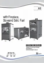
CS3311
CS4416
CS2307
7400100000R03
REV
PCN
DATE
00
~~~~
Feb 12, 07
01
11563
Aug 10, 09
02
11993
April 12, 10
03
Sept 4, 12
In keeping with our policy of continuous product development, we reserve the right to make changes without notice.
Dimplex North America Limited
1367 Industrial Road Cambridge ON Canada N1R 7G8
1-888-346-7539 www.dimplex.com
CS3311 Pictured
Summary of Contents for CS33116A
Page 5: ...5 Wiring Diagram ...