background image

COMPUTER-CONTROLLED INDOOR CYCLE
OWNER’S MANUAL

Summary of Contents for 910IC

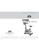
Page 1: ...COMPUTER CONTROLLED INDOOR CYCLE OWNER S MANUAL ...

Page 2: ...2 ...

Page 3: ...910Ic Owner s Manual 3 910Ic Computer Controlled Indoor Cycle Diamondback Fitness Release v 1 10 10 ...

Page 4: ...4 ...

Page 5: ...ioning during times of inclement weather or simply looking for new and different cross training options This trend still continues today twenty years later as the strong Diamondback brand resonates with both the boomers who grew up with the bicycles as well as the younger generations riding them today Diamondback Fitness continues to build upon this legendary brand identity by offering the cardio ...

Page 6: ...GUIDELINES 15 WORKOUT QUALITY AND QUANTITY 19 CONSOLE OVERVIEW GENERAL NOTES 20 CONSOLE LCD DISPLAY 20 CONSOLE KEYPAD FUNCTION 22 CONSOLE OPERATION AND FEATURES 22 PROGRAM CATEGORIES 24 TROUBLESHOOTING 29 MAINTENANCE 30 WARRANTY INFORMATION 30 WARRANTY REGISTRATION CARD 33 PURCHASER S REFERENCE INFORMATION 35 ...

Page 7: ...lt with a physician before beginning any exercise program If overweight or above the age of 35 consult with your physician before beginning an exercise program Pregnant women should consult with their physician before beginning an exercise program If you experience dizziness nausea chest pains or other abnormal symptoms during exercise stop the exercise session immediately and consult your physici...

Page 8: ...ys unplug the unit from the power source before moving or servicing Do not remove the covers or other components Only Authorized Diamondback Fitness Dealers or Authorized Technicians should perform service on the unit Assembly of Technical Items Assembly of all Diamondback Fitness products should be performed by a Diamondback Fitness Dealer or Authorized Technician A significant amount of technica...

Page 9: ...Screw 1 D Front Stabilizer Assembly 1 D 2 Leveling Foot Assembly 4 E Rear Stabilizer Assembly 1 F 16 Power Input Jack 1 F L R Pedal Clip Strap Assembly pair 1 G Main Frame 1 G 6 Stem Seat Post Adjustment Knob 2 H 1 Stabilizer Assembly Fixing Screw 8 H 2 Stabilizer Assembly Curved Washer 4 H 3 Stabilizer Assembly Flat Washer 4 H 4 Handlebar Assembly Fixing Screw 2 H 5 Handlebar Assembly Lock Washer...

Page 10: ...ng screws shown in Figure 1 above Discard this piece Align the front stabilizer D with the receiver located in the front of the frame and loosely install four 4 H 1 bolts two 2 curved washers H 2 and two 2 flat washers H 3 making sure that the correct shape of washers are installed on their corresponding surface profile i e flat washer on the flat surface etc When all bolts have been inserted tigh...

Page 11: ...fixing screws B 13 Thread all screws into place loosely before performing final tightening Remove the four console fixing screws A 1 from the back of the console A and set them aside Plug the upper wire harness connector B 17 into the back of the console A Make sure the connection is complete Position the console above the mounting plate located on the top on the stem assembly B 21 Reinstall the f...

Page 12: ...utward on the knob again Repeat these steps again if necessary Install the saddle L onto the seat post and tighten with the included wrench Install the pedals F L F R onto the cranks by threading the left pedal by hand marked with an L into the left crank with a counter clockwise rotation Do not cross thread the cranks pedals The pedal must be tight and installed completely to prevent future damag...

Page 13: ...ng care to ensure the connection is firm Remove handlebar assembly endcap fixing screw B 20 from the handlebar assembly endcap B 1 Insert the handlebar assembly endcap B 1 into the bottom of the handlebar assembly B 21 Reinstall the handlebar assembly endcap fixing screw B 20 through the base of the handlebar assembly B 21 to secure the endcap ...

Page 14: ...ng the assembly pull the knob outward away from the frame to disengage the pop pin Raise or lower the assembly as desired releasing the knob to reengage the pop pin Tighten the knob to lock the assembly in place Final Adjustments Fore Aft Fore aft adjustment for the seat and handlebar are made by loosening the levers B 4 located under the assemblies Rotate the lever to the left to loosen If the le...

Page 15: ...0 240 250 4 6 29 31 34 36 39 41 43 46 48 51 53 56 58 60 Height in Feet and Inches 4 8 27 29 31 34 36 38 40 43 45 47 49 52 54 56 4 10 25 27 29 31 34 36 38 40 42 44 46 48 50 52 5 0 23 25 27 29 31 33 35 37 39 41 43 45 47 49 Healthy Weight 5 2 22 24 26 27 29 31 33 35 37 38 40 42 44 46 5 4 21 22 24 26 28 29 31 33 34 36 38 40 41 43 Overweight 5 6 19 21 23 24 26 27 29 31 32 34 36 37 39 40 5 8 18 20 21 23...

Page 16: ... compatible heart rate chest strap transmitter not included must be functioning and worn For proper function of the chest strap please refer to the manufacturer s instructions Non coded transmitters such as the Polar model T31 and T34 are examples of wireless chest straps known to be compatible with this unit The unit must be powered on A workout program must be running The user is within three 3 ...

Page 17: ... slow the progression of your exercise goals as the body attempts to recover Note It is most effective to train at a heart rate between 60 and 85 of your maximum heart rate Maximum heart rate is calculated as a percentage of your maximum heart rate estimated as 220 beats per minute minus your age To calculate your maximum heart rate and find the appropriate target training zone use the following f...

Page 18: ...culations the recommended heart rate training zone for this user would be between 111 Bpm 157 Bpm The graph below displays the recommended heart rate training zone for users twenty years of age to seventy five years of age ...

Page 19: ...nt at home offers you the opportunity to work out without going to the gym Get a Smart Start on Exercising Anyone over the age of 35 as well as younger persons whom are overweight should check with his her physician before commencing an exercise program Persons who have diabetes or high blood pressure a family history of heart disease high cholesterol or have led sedentary lifestyles should protec...

Page 20: ... the battery ever run down or if the console does not light connect the included power supply adaptor to a 120V power source Plug the opposite end into the 910Ic power input jack found near the ground at the rear of the machine Begin pedaling to recharge the battery To avoid damage and danger use only the power supply adaptor that was designed for the 910Ic To maintain and extend the life of the b...

Page 21: ...splayed in beats per minute The signal has to receive a heart rate between 30 BPM and 240 BPM to register When a heart rate is detected by the console the heart symbol will flash A wireless heart rate transmitter such as the Polar un coded T31 or T34 is required for the heart rate monitoring function to operate Calories The total calories burned since the program launch will be displayed in the Ca...

Page 22: ...STOP key again will restart console and return the display to the main screen Up Down Arrow Keys The UP and DOWN arrow keys allow the user to adjust the on screen values in the program setup mode While operating the Heart Rate Control program the arrow keys will adjust the target heart rate During all other programs the arrow keys will increase or decrease the resistance CONSOLE OPERATION AND FEAT...

Page 23: ... H R C Heart Rate Control PROGRAM Preprogrammed Profiles and USER User Defined Custom Within these categories H R C and PROGRAM offer several options see the chart to the right When the unit is powered on the small cluster of program titles on the LCD display will flash prompting the user to make a selection QuickStart If the START STOP key is pressed while the main screen is displayed the console...

Page 24: ...ble settings TIME DISTANCE CALORIES WATTS PULSE TIME The user may adjust any number of these targets or accept the current default values and press the START STOP key to launch the program Workout Time Setting Once the Manual program has been selected pressing the ENTER key will launch the setup mode TIME will flash on the console display with the default value of twenty four 24 minutes Increase a...

Page 25: ...t target If the Watts being generated are below the target the Down arrow will flash to indicate that the user is not generating enough Watts The user should increase their RPM to maintain the Watts target If the situation continues for more than three 3 minutes the monitor will give six beeps switch itself off and reset the Watt value back to zero A flashing circle will indicate that the Watts ta...

Page 26: ...d profile is displayed Adjust the resistance level via the UP and DOWN arrow keys or press ENTER to select the profile as displayed Launch Pressing the START STOP key will immediately launch the program Adjustments to the resistance are made via the UP and DOWN arrow keys Custom Targets If the user would like to customize the current program parameter such as the workout Time period or incorporate...

Page 27: ...lumn or time segment will flash prompting the user to adjust the resistance via the UP and DOWN arrow keys Make the desired adjustment to this segment and move to the next by pressing the ENTER key Repeat these steps for all sixteen 16 segments Custom Targets To customize the program metrics such as the workout Time period or incorporate Distance Calorie or Watt generation targets press and hold t...

Page 28: ... computer then determines which heart rate represents 55 70 and 90 of the user s calculated maximum The T H R Target Heart Rate program differs from the percentage programs in that the user will set a numeric value for their targeted heart rate Resistance will be controlled by the unit to help maintain the user s target pulse rate To select one of the H R C program highlight the H R C category in ...

Page 29: ... Test program press the FIT TEST button on the keypad A one minute timer will begin to count down Only the countdown clock value and current heart rate will be displayed When the program concludes your relative fitness rating will be displayed in the Matrix Display Brickyard The returned values range from F1 to F6 See the chart above This rating is only a guideline and not meant to serve as profes...

Page 30: ...n can be extremely corrosive if allowed to accumulate on the machine After training always wipe down the unit with a mild soap solution followed by a thorough drying with a clean towel Locating a small spray bottle and towel near the unit will help ensure that your Diamondback Fitness equipment looks new for many years NOTE Perspiration is very corrosive and if allowed to remain on the machine wil...

Page 31: ...e Limited lifetime warranty Parts Electronics 3 years Labor 1 year Wear Items 90 days Note Limited lifetime refers to warranty coverage of the unit s expected service life not the lifetime of the purchaser The expected lifetime of this unit is five 5 years from the date of purchase although other factors can extend this period Support and maintenance of the unit may become difficult or impossible ...

Page 32: ...s unit is employed for commercial or rental purposes This unit is for indoor use only Additional Rights This Warranty is expressly in lieu of all other warranties and any implied warranties of merchantability or fitness for a particular purpose created hereby and are limited to the same duration as the express warranty herein Diamondback Fitness shall not be liable for any incidental or consequent...

Page 33: ... com Name last first Address City State Zip Code Daytime Telephone Evening Telephone _______________________________________________________________________________ Dealer Store Name Dealer s Address City State Zip Code _______________________________________________________________________________ Model 910Ic Serial Number E Date of Purchase Mail Completed Form To Diamondback Fitness Warranty Car...

Page 34: ...34 ...

Page 35: ...he event the unit requires future service ATTACH THE PURCHASE RECEIPT Dealer Name ___________________________________________ Dealer Telephone Number __ ____________________________ Dealer Address ______________________________________________________________________________________________________ Date Purchased _________________________________________ Dealer Contact Name _______________________...

Page 36: ... Diamondback Fitness 2010 DP 22 10 1264 DIAMONDBACK FITNESS 6004 S 190th Street Suite 101 Kent WA 98032 Ph 800 776 7642 ...

Reviews: