background image

1

KSM-KH Installation Guide

Package Contents

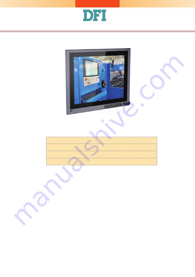
• One 15", 19", or 21.5" Modular Touch Panel PC
• Power cable with 3-plole teminal block connector
• SATA, Mini PCIe and M.2 Installation Screws
• Extended power switch cable

DFI reserves the right to change the specifications at any time prior to the 

product's release. For the latest revision and more details of the installation 

procedure, please refer to the user's manual on the website.

www.dfi.com

Summary of Contents for KSM-KH Series

Page 1: ...nal block connector SATA Mini PCIe and M 2 Installation Screws Extended power switch cable DFI reserves the right to change the specifications at any time prior to the product s release For the latest revision and more details of the installation procedure please refer to the user s manual on the website www dfi com ...

Page 2: ...conds 2 Light Sensor On Off Press the Brightness up arrow for 3 seconds 3 OSD Lock Unlock Press the Brightness down arrow for 3 seconds 4 The Alarm LED has no funtion for the KSM KH Series Backlight or Power on off Volume Brightness Power HDD Alarm LED Bottom View Top View DC in USB 3 0 DVI D DVI I connector LAN 1 LAN 2 VGA HDMI KSM 190 COM 2 Power Button 1 Reset Button COM 3 COM 4 Status LED Oran...

Page 3: ...powered off 2 Disconnect all power cords and cables 3 Remove mounting screws at each side of the system box 4 Lift the cover to open the system 5 The Mini PCIe M 2 and the SODIMM slots are readily accessible after removing the chassis cover SODIMM Socket Mini PCIe Sockets M 2 Socket SATA drive bay SIM card slot ...

Page 4: ...f the SATA drive Then install the SATA drive onto the HDD bracket with the provided mounting screws Installing a SATA Drive Mounting Screws Mounting screws SATA data and power cable 2 Place the SATA drive installed with the HDD bracket in the system Align the mounting holes on the HDD bracket with the mounting holes on the drive bay and use the provided mounting screws to secure the drive in place...

Page 5: ...5 3 Connect the other end of the SATA data power cable to the SATA data and power connectors on the system board respectively SATA power connector SATA data connector ...

Page 6: ... SODIMM module installed into the socket Notes 1 The system supports dual channel configuration To enable dual channel populate both SODIMM sockets 2 If installing only one memory module please install it on the memory socket labeled DIMM 1 the one closer to the center of the board 3 The SODIMM sockets can only accept DDR4 memory modules Please do not install other types of memory modules The SKUs...

Page 7: ... 2 card into the connector and then secure the card to the standoff with the provided mounting screw Mounting Screw The onboard M 2 Type 2280 connector M Key supports PCIe NVMe modules up to PCIe Gen 3 0 x4 bandwidth Note that only SKUs with Intel QM175 Chipset support M 2 socket ...

Page 8: ...interfaces whereas Mini PCIe slot 2 provides only USB interface 1 Grasp the Mini PCIe card by its edges and align the notch in the connector of the Mini PCIe card with the notch in the connector on the system board 2 Push the Mini PCIe card down and use the provided mounting screws to secure the card on the system board Mounting screws Installing a Mini PCIe Card and a SIM Card Mini PCIE2 Mini PCI...

Page 9: ...acing down and the angled corner aligning with the socket s angled corner so it will be correctly in contact with the system board Close the slot s cover and lock the slot by pushing the white latch outward Close the cover and lock it Mini PCIE2 Mini PCIE1 Push the latch inward to open it Push the latch outward to close it Flip the cover up to open it ...

Page 10: ...enly on top of the panel module which results in some space in between them and indicates that the ADP connectors are not engaged When this is the case please turn the box module the other way around Alignment Post 2 Hold the box module with its ADP connector female in line with the ADP connector male of the panel module Align the box module with the panel module using the alignment posts Box Modu...

Page 11: ...the panel module with the alignment post effortlessly sliping into the designated holes on the box module Press to install these two modules and secure the installation with 8 mouting screws Mounting Screw Mounting Screw Alignment Post Box Panel Module ...

Page 12: ... following 2 VESA mount brackets Bracket screws 2 Select a place on the wall where you will mount the Panel PC 3 Use the provided mounting screws to attach VESA mount bracket 1 to the wall Mounting Options VESA mount VESA mount bracket 1 VESA mount bracket 2 VESA mount bracket 1 Mounting screw 1 Before starting any installation procedures attach the poron foam to the Panel PC Poron foam ...

Page 13: ...lide the Panel PC to wall mount bracket 1 to attach the two brackets with the hooks Then tighten the thumb screw to secure the assembly in place Note that the following diagram is for illustration only and may not resemble the actual product Thumb screw VESA mount bracket 2 Thumb screw Hooks Mounting screw ...

Page 14: ...ns 15 367mm x 300mm 18 5 454mm 296mm 19 447mm x 380mm 21 5 526 2mm x 342 6mm and ensure that the Panel PC can be fitted into the panel properly 4 Insert the Panel PC from the outside surface of the panel into the mounting hole until it is properly fitted against the panel 5 Position the mounting clamps along the rear edges of the Panel PC and insert them into the slits around the Panel PC Note tha...

Page 15: ...o mounting the rest of the clamps Tighten the clamp s screw using an electric screwdriver by pressing the flat cap onto the back of the panel cap Slit for mounting the clamp Mounting clamp Note The maximum thickness of your panel s mounting wall should be 10 mm for secure panel mount ...

Page 16: ...pin Notes 1 The DVI D port can be in HDMI or DVI D 2 The HDMI is a DP HDMI combo port but can only transmit HDMI signals unless wired as a DP port Please plug in an HDMI cable with the right orientation and alignment to avoid damage to the connector You should feel resistance due to a pin on the right if the cable is not inserted correctly Please see a video at https youtu be SUj07rfN5l8 for detai...

Page 17: ...4 6 12V On PS 2 KB MS Power source JP14 5V 1 2 On 5V_Standby 2 3 On Notes 1 When COM1 RS232 422 485 is selected JP9 and JP15 must be set in accordance to JP10 2 When COM2 RS232 422 485 is selected JP11 and JP17 must be set in accordance to JP16 3 When COM3 RS232 422 485 is selected JP12 and JP18 must be set in accordance to JP13 4 When COM4 RS232 422 485 is selected JP6 and JP19 must be set in acc...

Reviews: