Dexing Fiber Labs NDS3332, User Manual
The Dexing Fiber Labs NDS3332 is a cutting-edge network data switch designed for high-speed data connectivity. To learn more about how to optimize its performance, be sure to download the free User Manual from our website. Get the most out of your NDS3332 with our comprehensive manual.
Share
Download


Reviews:
No comments
Related manuals for Fiber Labs NDS3332
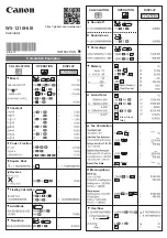
WS-1400H
Brand: Canon Pages: 2
P1-DTSC
Brand: Canon Pages: 2
MP27-MG
Brand: Canon Pages: 2
MP25-MG
Brand: Canon Pages: 2
MP18DII
Brand: Canon Pages: 2
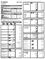
MP11DX - Printing Calculator
Brand: Canon Pages: 4
LS-270H
Brand: Canon Pages: 2
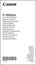
F-789SGA
Brand: Canon Pages: 40
F-719SG
Brand: Canon Pages: 2
WS-1210Hi III
Brand: Canon Pages: 2

Radyne DM240XR
Brand: Comtech EF Data Pages: 222

HP-41CX
Brand: HP Pages: 21

HP-67
Brand: HP Pages: 18

HP-41 C
Brand: HP Pages: 7

HP-41 C
Brand: HP Pages: 45

HP 9s
Brand: HP Pages: 5

HP-33C
Brand: HP Pages: 103

HP-10C
Brand: HP Pages: 127


