


P/N 125166
REV. 11/07
C-159
LCC SERIES OVENS
INSTRUCTION MANUAL
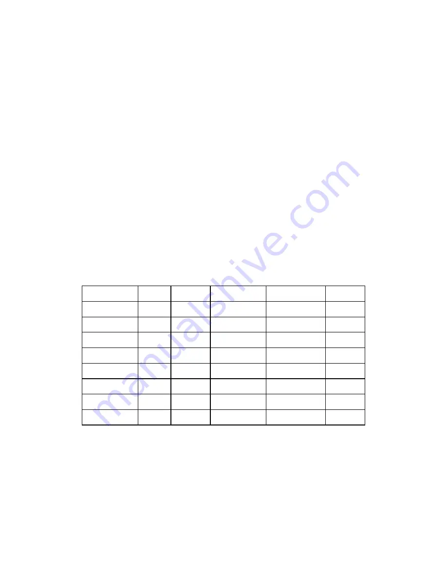
Model
Volts
Phase
Hz
Heater Watts
Total
LCC 1-11
240
1
50/60
3,000
14.2
LCC 1-11N
240
1
50/60
3,000
14.2
LCC 1-54
240
1
50/60
6,000
26.7
LCC 1-54N
240
1
50/60
6,000
26.7
LCC 1-54NV
240
1
50/60
6,000
26.7
LCC 1-87
240
1
50/60
9,000
42.2
LCC 1-87N
240
1
50/60
9,000
42.2
LCC 1-87NV
240
1
50/60
9,000
42.2
Prepared by:
Despatch Industries
P.O. Box 1320
Minneapolis, MN 55420-1320
Customer Service 800-473-7373


